


937A Multi-Sensor System
A.5
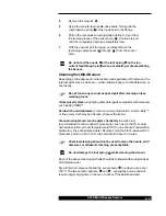
Leaf spring in
contact with
cathode
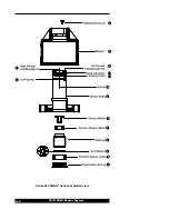
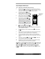
Assembling the I-MAG Sensor
Wear gloves and assemble with clean tools.
1
Roll the
sensor body on a flat surface and, looking down the port,
check the
anode for any radial runout motion. It should be straight
and centered with the
sensor body for proper operation.
2
Install the
ground shield using
tweezers. Make sure that the
ground
shield drops into the locating collar .
3
Slide the
small ceramic spacer over
the small end of the
ground shield .
4
Check that the
leaf spring will
contact the base of the
cathode as
shown to the right. If not, remove the
small ceramic spacer and the ground
shield, and gently bend the leaf spring
towards the
anode and then replace
the
ground shield and ceramic spacer.
5
Slide the
cathode , the grid washer
,and the
large ceramic spacer into
place. The
grid washer has a concave shape. Refer to the figures to
see its installation orientation.
6
Insert the small end of the
compression spring into the sensor
body .
7
Using your thumbs, push the larger end of the spring into the
sensor
body until it is contained within the tube's inside diameter.
8
Using the smooth-jaw, needle-nose pliers, work the
compression
spring down into the sensor body until it is fully seated in the formed
groove.
9
Inspect the
ground shield and the grid washer to verify they
are centered with respect to the
anode .
10
If adjustment is needed, gently reposition the grid washer/cathode
assembly, taking care not to scratch the
grid washer.
We suggest you measure the resistance between the
ion current feedthrough
pin and the grid washer to verify that the leaf spring is in contact
with the
cathode . The measurement should indicate a short circuit
between them. There should be an open circuit between the
ion current
feedthrough pin and both the high voltage feedthrough pin and sensor
body .
8
11
7
6
5
6
9
4
8
4
3
2
1
7
6
3
9
4
13
13
10
7
8
3