


32
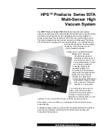
937A Multi-Sensor System
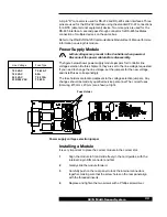
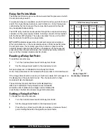
RS-485 communications at high speed and over long wires may require both
ends of the cable to be terminated with its characteristic impedance. Holes
marked
R1 on the module are for a termination resistor if needed. For twisted
pair wire,120 ohms should be used.
This resistor should only be used on the module at the end of
the transmission line.
If a parity error occurs in a command sent to the Controller, it will discard all
characters received and wait for another command. No error message or other
response is sent back to the host computer. Use of parity is recommended.
See the section on Parity in the
RS-232/RS-485 Communications Module
User's Manual for more information.
Since the simple protocol does not require attention and address characters,
the remaining portion of a faulty command may be misinterpreted. Therefore,
with a parity error, the Controller may respond differently from what's
expected.
To avoid this, the more robust multidrop protocol may be used with a RS-232
interface.
1
Set module switches 5 and 7 to On.
2
Set 6 to Off.
3
Use attention and address characters with RS-232
wiring and signal levels.
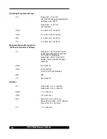
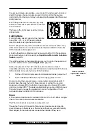
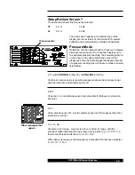
ELECTRICAL INTERFACE AND LOGICAL PROTOCOL
CONNECTION TYPE
SWITCH POSITION
SWI SETTING
Normal RS-232
Simple Protocol
5
Off
Rs-232 Interface
6
Off
7
On
Normal RS-485
Multidrop Protocol
5
On
RS-485 Interface
6
On
7
Off
5
On
RS-232 Interface with
6
Off
Multidrop Protocol
7
On
Bit Rate and Parity Selection
SWI Seting
1
None
Even
None
Even
None
Even
None
Even
2400
4800
9600
19,200
1
On
2,3,4
Off
1
Off
2,3,4
On
2
On
1,3,4
Off
2
Off
1,3,4
On
3
On
1,2,4
Off
3
Off
1,2,4
On
4
On
1,2,3
Off
4
Off
1,2,3
On
Bit
Rate
Parity
Switch
Position
1. Note: other combinations will default
to 9600bps parity