


60
937A Multi-Sensor System
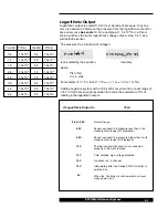
Controller Analog Output
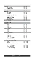
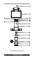
The chart identifies the pins of the female, 25-pin "D"
connector on the Analog Module.
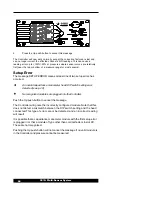
Buffered and logarithmically scaled analog outputs are
available from each sensor. Wide range combination output is
also available from each cold cathode sensor with a
combination sensor.
For twisted pair connection, an analog ground pin is provided
for each output signal. The Analog Module connector also
has a high voltage disable input and ground for the Slot
CC
Cold Cathode Module.
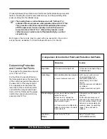
Buffered Output
See Appendix C for voltage-vs-pressure curves from the buffered
analog output for each sensor. These signals are not affected by
vacuum or atmospheric calibration. The table below shows analog
output values for various sensor conditions.
* Pin 9 provides this function only
when a cold cathode sensor is
installed in slot A.
Pin
Description
1
analog output, combination, channel CC
2
analog output, buffered, channel CC
3
analog output, buffered, channel A1
4
analog output, buffered, channel A2
5
analog output, buffered, channel B1
6
analog output, buffered, channel B2
7
analog output, logarithmic, channel CC
8
analog output, logarithmic, channel A1
9
analog output, logarithmic, channel A2
9*
analog output, combination,channel A1
10
analog output, logarithmic, channel B1
11
analog output,logarithmic, channel B2
12
not used
13
cold cathode disable,slot CC
14-24
analog ground
25
cold cathode disable return,slot CC
If Buffered
Then
Output is
0 to 10 V Normal Range
Cold Cathode
No discharge or a pressure reading of less
than
< 0 V
Capacitanc Manometer
Reading below 0 Torr (zero adjustment at
head may be needed)
Cold Cathode
High voltage disabled
> 10 V
Thermocouple
Not properly connected