


34
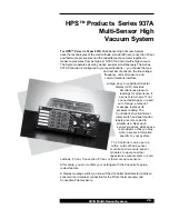
937A Multi-Sensor System
A change of pressure units, module type, or capacitance manometer head
range may invalidate user calibration and setpoint values. If the set point
value is within the acceptable range, it will remain the same numeric value. If
it is not within the acceptable range, then the setpoint will be disabled and
reset to 0.0 . If the type of sensor module or capacitance manometer head
range is changed, any calibration values previously set will be returned to the
factory calibration value. Reset values if necessary.
When removing one type of sensor module and installing
another type, or when changing the pressure units (Torr, micron,
etc.), set point values are not automatically converted.
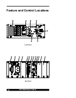
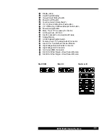
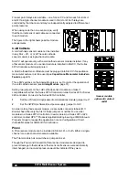
Panel Labels
Five white labels are located on the far left of the front panel for user
notations, such as type and location of sensors, set point values, calibration
status, or other pertinent information. Write with a standard pencil on the
labels or apply preprinted adhesive labels. Remove pencil marks with
isopropyl alcohol, glass cleaner, or a pencil eraser.
Do not use acetone to clean the front panel.
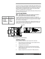
Mounting the Controller
The 937A was designed for either rack mounting or for benchtop use.
Regardless of the method you choose, to assure adequate ventilation to the
Controller, leave at least 1 inch open above the perforated panels. Side
clearance is not required.
To accommodate connectors and cables, leave open about 3 inches of
clearance behind the rear panel.
For benchtop use, adhesive backed rubber pads are provided. Remove
the adhesive backing from each pad and apply one to each corner of
the bottom surface.
Optional mounting hardware is available for mounting the Series 937A
controller in a 19 inch rack.
Labels