


33
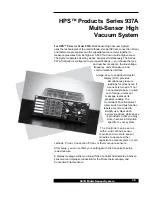
937A Multi-Sensor System
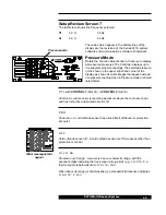
A 9-pin "D" connector is used for RS-232 and RS-485 serial interfaces. Three
pins are used for the RS-232 interface using the standard PC-AT connections
for a DTE (data terminal equipment) device. Two more pins are used for the
RS-485 interface. A second pass-through connector for RS-485 facilitates
connection of multiple devices on the same bus.
Refer to the
RS-232/RS-485 Communications Module User's Manual for more
information on using this module.
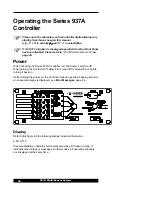
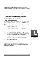
Power Supply Module
Lethal voltages are present in the Controller when powered.
Disconnect the power cable before disassembly.
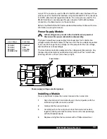
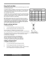
The figure below shows power supply module jumpers for Controller line
voltage selection. Before shipment, they are set to the line voltage requested.
If you need to change the line voltage, set the jumpers for the new voltage,
and install fuses correspondingly.
The fuse holders are located adjacent to the voltage selection jumpers. Any
changes should be made by qualified service personnel. The correct fuses
(time-lag, Ø 5 mm x 20 mm) are shown at right.
Installing a Module
It is very important to place the correct module in the correct slot.
1
Align the module to fit and slide freely in the card guides, with the
internal 32-pin DIN connector end first.
2
Gently slide the module forward.
3
Carefully push on the rear panel to lock the internal connectors
together, making sure that the screw holes on the rear panel align
with the threaded inserts.
4
Replace and tighten the two screws with a Phillips screwdriver.
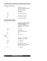
Fuse Holder
Power supply voltage selection jumper
Fuse Type
T 0.63A T
0.5A
T 0.315A
T 0.25A
Line Voltage
100 VAC
120 VAC
220 VAC
230/240 VAC