366
FX
3U
/FX
3UC
Series Programmable Controllers
Programming Manual - Basic & Applied Instruction Edition
14 Handy Instruction – FNC 60 to FNC 69
14.1 FNC 60 – IST / Initial State
14.1.1
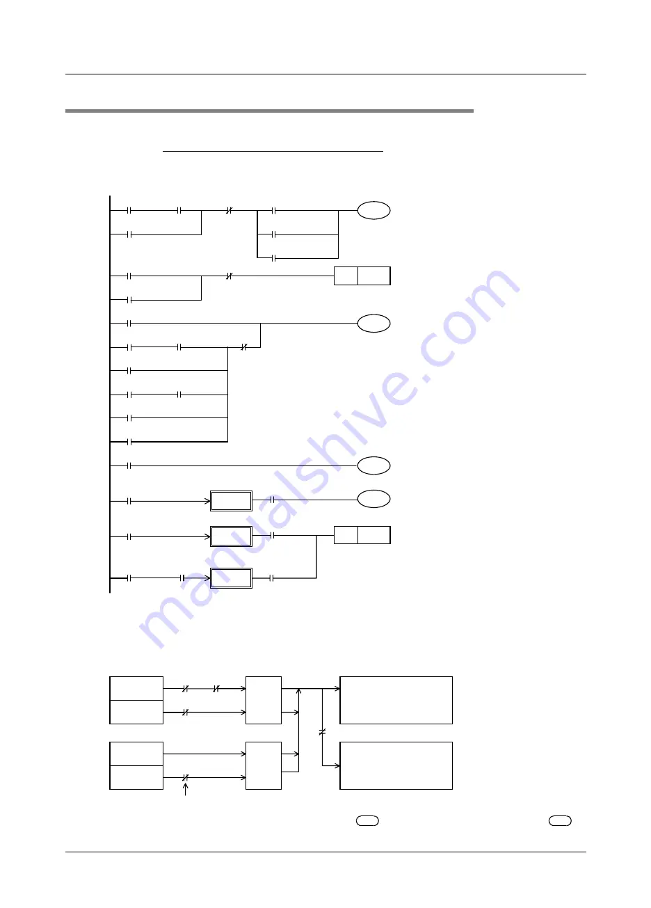
IST instruction equivalent circuit
The details of special auxiliary relays (M) and initial state relays (S0 to S9) which are automatically controlled
by IST instruction are as shown in the equivalent circuit below. (Refer to the equivalent circuit below for
reference.) This equivalent circuit cannot be programmed.
1. Equivalent circuit
2. Switching of the operation mode
When the operation mode is switched among the individual operation, zero return operation and automatic
operation, all outputs and conventional states are reset at one time unless the machine is located in the zero
point. (Reset of all outputs
*1
is not executed when M8045 is driven.)
*1.
All outputs: Outputs (Y) not driven by state relays
and outputs (Y) driven by state relays
in
OUT and SET instructions
X024
M8041
M8041
Continuous
operation
X027
M8041 is set to ON when the start button
is pressed in the automatic mode.
Especially in the continuous mode,
M8041 holds its status by itself, and is
reset when the stop button is pressed.
Stop
X022
Stepping
operation
X023
Cycle
operation
X024
Continuous
operation
Transfer
start
X026 Automatic start
X026 Automatic start
X020
Individual
operation
Start pulse
X025 Zero return start
M8042
X020
M8040
Individual operation
STL transfer
disable
X021
Zero
return X027
M8042
Start pulse
Stop
X022Stepping operation
X023Cycle
operation
X027Stop
M8002 Initial pulse
M8040 Self-holding
M8000
M8047
RUN monitor
Enable STL monitoring
X020
Individual
operation
S 0
M8044
Zero point
condition
M8043
Zero return
complete
X021 Zero return
S 1
X025
Zero return
start
Zero return
complete signal is
reset
M8043
RST
PLS
X022 to X024
Automatic
operation
Zero return
complete
M8043
M8041
Transfer start
S 2
M8040 is set to ON in the stepping
mode, and set to OFF every time the
start button is pressed.
In the zero return operation or cycle
operation, M8040 holds its status by
itself when the stop button is pressed,
and is reset when the start button is
pressed.
The initial state is switched according to
each mode input, and M8043 is
controlled at the same time.
However, it is necessary to control
M8044 and M8043 in user programs
also.
*1
*1
*1
*1
*1. Because the above equivalent circuit is provided only for explanation, it cannot be actually programmed.
Zero return
X021
Automatic
X022 to X024
S1
M8043
Switched
to X020
(individual
operation)
Zero return
complete
S2
Conventional states and
corresponding outputs are
reset at one time.
Individual
operation
X020
Automatic
X022 to X024
Switched
to X021
(zero
return
operation)
S2
When M8045 is OFF, all
outputs are reset.
All output reset disable
M8045
Even if the mode is switched from automatic operation to zero return operation while S2 is ON, state relays
(except initial state relays) and outputs are not reset.
D
1
S
D
1
S


