211
FX
3U
/FX
3UC
Series Programmable Controllers
Programming Manual - Basic & Applied Instruction Edition
8 Program Flow – FNC 00 to FNC 09
8.8 FNC 07 – WDT / Watchdog Timer Refresh
1
In
troduct
io
n
2
Ov
e
rv
ie
w
3
In
st
ru
ct
ion
Li
st
4
D
evi
ce
s
in
De
ta
il
5
Speci
fied t
h
e
D
evi
ce &
C
onst
a
nt
6
Bef
o
re
Pr
ogr
a
m
m
ing
7
Bas
ic
In
st
ru
cti
o
n
8
FNC0
0
-FNC0
9
P
ro
g
ra
m F
lo
w
9
FNC1
0
-FNC1
9
M
ov
e
&
C
om
par
e
10
FNC
20-
FNC
2
9
Ar
ith.
&
Logi
c
O
per
at
io
n
Cautions
1. When a watchdog timer error occurs
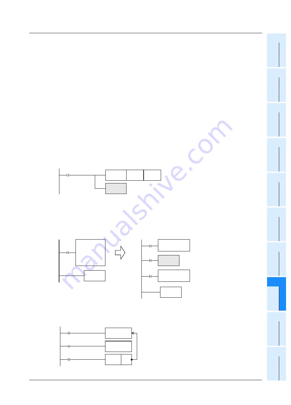
A watchdog timer error may occur in the following cases. To avoid the error, input a program shown below
near the head step to extend the watchdog timer time, or shift FROM/TO instruction execution timing.
1) Caution when many special extension devices are connected
In such configuration that many special extension devices (such as positioning units, cam switches,
analog units and link units) are connected, the buffer memory initialization time may become longer, thus
the operation time may become longer, and a watchdog timer error may occur.
2) Caution when many FROM/TO instructions are driven at one time
When many FROM/TO instructions are executed or when many buffer memories are transferred, the
extension time may become longer, and a watchdog timer error may occur.
3) Caution when there are many high speed counters (software counters)
When many high speed counters are provided and high frequency are counted at one time, the operation
time may become longer, and a watchdog timer error may occur.
2. The watchdog timer time can be changed.
→
For the details of changing watchdog timer time, refer to Subsection 36.2.2.
By overwriting the contents of D8000 (watchdog timer time), the watchdog timer detection time (initial value:
200 ms) can be changed.
By inputting the program shown below, the sequence program after this insertion is monitored by a new
watchdog timer time.
Program examples
1. When the operation cycle is long and causes an error
For example, by dividing a program whose operation cycle is 240 ms into two portions and inserting WDT
instruction between them, the operation cycle becomes less than 200 ms in both the former half portion and
the latter half portion.
2. When a label (P) of CJ instruction is located in a step number smaller than the step number
of CJ instruction
Put WDT instruction after the label (P).
If an input relay (X) is used as the
command contact, input refresh is
disabled, so the program execution
cannot be returned from the area
between P and CJ.
As the command contact, use such
device that can be set to OFF in a
program being jumped.
M8002
Initial pulse
FNC 12
MOV
K300
D8000
FNC 07
WDT
Watchdog timer time: 300 ms
0
Watchdog timer refresh
If WDT (FNC 07) instruction is not programmed, the value of
D8000 is valid during END processing.
FNC07
WDT
END
Program
whose
operation cycle
is 240 ms
END
Program whose
operation cycle
is 120 ms
Program whose
operation cycle
is 120 ms
M8000
RUN monitor
FNC 07
WDT
Label
Pn
Command
Program
FNC00
CJ
Pn
When the command
contact turns ON


