SmartTime Static Timing Analyzer User Guide
76
A green check mark appears next to Place and Route after successful completion of Place and Route.
Maximum Delay Analysis with Timing Analyzer- 32-Bit Shift
Register Example
The SmartTime Maximum Delay Analysis window displays the design maximum operating frequency and
lists any setup violations.
To perform Maximum Delay Analysis:
1. Right-click
Open SmartTime
in the Design Flow window and choose
Open Interactively
to open
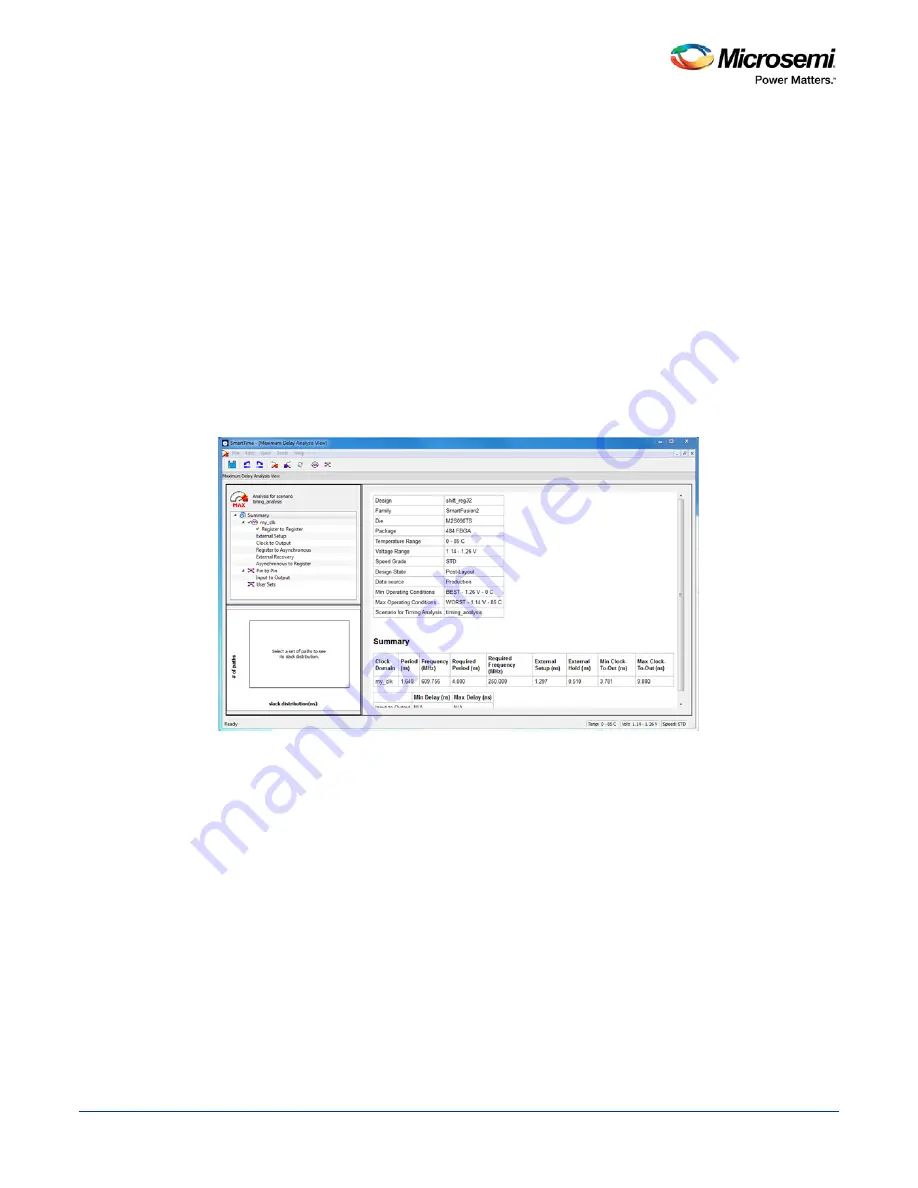
SmartTime. The Maximum Delay analysis window appears. A green check next to the clock name
indicates there are no timing violations for that clock domain. The Summary page displays a summary
of the clock domain timing performance.
The Maximum Delay Analysis Summary displays:
•
Maximum operating frequency for the design
•
External setup and hold requirements
•
Maximum and minimum clock-to-out times. In this example, the maximum
clock frequency for CLK is 609.75 MHz.
Figure 50 · Maximum Delay Analysis - Summary
2. Expand
my_clk
to display the Register to Register, External Setup and Clock to Output path sets.
3. Select
Register to Register
to display the register-to-register paths. The window displays a list of
register-to-register paths and detailed timing analysis for the selected path (as shown in the figure
below). Note that all the slack values are positive, indicating that there are no setup time violations
Summary of Contents for SmartTime
Page 2: ......
Page 6: ......
Page 15: ...SmartTime Static Timing Analyzer User Guide 15 SmartTime Timing Analyzer ...
Page 31: ...SmartTime Static Timing Analyzer User Guide 31 Advanced Timing Analysis ...
Page 37: ...SmartTime Static Timing Analyzer User Guide 37 Generating Timing Reports ...
Page 57: ...SmartTime Static Timing Analyzer User Guide 57 Timing Concepts ...
Page 66: ...SmartTime Static Timing Analyzer User Guide 66 ...
Page 92: ...SmartTime Static Timing Analyzer User Guide 92 Dialog Boxes ...
Page 118: ...SmartTime Static Timing Analyzer User Guide 118 Tcl Commands ...


