Operator Maintenance 95
_______________________________________________________________________________________________
_______________________________________________________________________________________________
MICROPLEX
Operator‘s Manual SOLID T4 / T5 / T6 / T8
Edition 2.0
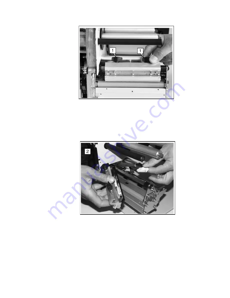
Fig. 7.2.1.a Unscrewing the two thumb screws
6. The printhead is provided with two lead wires. Pull out both
plugs in a horizontal direction from the printhead.
7. Remove the old printhead from the device.
Fig. 7.2.1.b Removing the printhead
8. Take the
new printhead
and note the
resistance-
value
printed on the new printhead due to the later setting
(inscription: R = ..., value in Ohm).
9. Connect the new printhead to the printer using the two plug
connections.
Summary of Contents for LOGIJET T4
Page 108: ......


