Electrical Installation Safety Trainer
AD 1 - MI 3399
97
2.6.2.3 Exercise No. 2.6-3: R
ISO
in an IT system
Measuring procedure
1
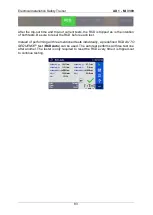
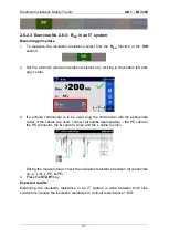
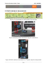
To measure the insulation resistance select first the
R
ISO
function in the
ISO
section.
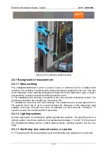
2
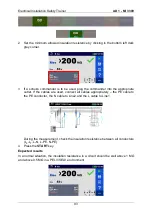
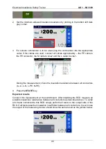
Set the minimum allowed insulation resistance by clicking in the bottom left dark
grey corner.
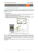
3
If a schuko commander is to be used, plug the commander into the appropriate
outlet. If the cables are used, connect all cables appropriately
– the PE cable to
the PE conductor, the N cable to Line2 and the L cable to Line1.
During the measurement, check the insulation resistance between all conductors
(L
X
-L
Y
, L-N, L-PE. N-PE).
4
Press the
START
key.
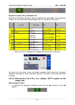
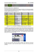
Expected results
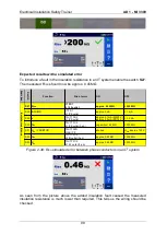
Measuring the insulation resistance in an IT system is done between both Line
conductors. Usually the insulation resistance in a circuit is well above 1 M
Ω.
Summary of Contents for MI 3399
Page 27: ...Electrical Installation Safety Trainer AD 1 MI 3399 27...
Page 46: ...Electrical Installation Safety Trainer AD 1 MI 3399 46 3 Exit settings...
Page 74: ...Electrical Installation Safety Trainer AD 1 MI 3399 74...
Page 197: ...Power and Voltage Quality Trainer AD 2 MI 3399 197 Figure 4 89 Transient Chart view...
Page 204: ...PAT Appliances Machines Safety Trainer AD 3 MI 3399 204...
Page 249: ...PV Photovoltaic Systems Trainer AD 4 MI 3399 249...
Page 250: ...PV Photovoltaic Systems Trainer AD 4 MI 3399 250 AD 4 MI 3399 PV Photovoltaic Systems Trainer...

