Electrical Installation Safety Trainer
AD 1 - MI 3399
51
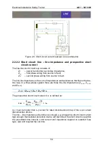
Figure 2-6: Short circuit current between two Phase conductors
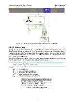
2.2.2.3 Voltage drop
During the Z
LINE
measurement the fuse before the measured circuit is the one
referenced to. When measuring Z
LINE
on the supply conductor, the fuse prescribed by
the electrical distributor is considered. When measuring Z
LINE
on the circuit the fuse
installed before that circuit is considered. The difference between both measurements
must not be greater than 3%.
After the reference impedance (Z
REF
) has been determined the actual voltage drop test
may be performed. The voltage drop is calculated as follows:
𝛥𝑈[%] =
(𝑍 − 𝑍
𝑅𝐸𝐹
) ∙ 𝐼
𝑁
𝑈
𝑁
∙ 100 < 3%
where:
ΔU
– Voltage drop,
Z
– Measured line impedance,
Z
REF
– Reference line impedance,
I
N
– rated current of selected fuse,
U
N
– nominal voltage (see Table 2-1).
U
N
Input voltage range (L-N or L1-L2)
110 V
93 V <= UL-N < 134 V
230 V
185 V <= UL-N <= 266 V
400 V
321 V < UL-L <= 485 V
Table 2-1: Nominal voltage table
Summary of Contents for MI 3399
Page 27: ...Electrical Installation Safety Trainer AD 1 MI 3399 27...
Page 46: ...Electrical Installation Safety Trainer AD 1 MI 3399 46 3 Exit settings...
Page 74: ...Electrical Installation Safety Trainer AD 1 MI 3399 74...
Page 197: ...Power and Voltage Quality Trainer AD 2 MI 3399 197 Figure 4 89 Transient Chart view...
Page 204: ...PAT Appliances Machines Safety Trainer AD 3 MI 3399 204...
Page 249: ...PV Photovoltaic Systems Trainer AD 4 MI 3399 249...
Page 250: ...PV Photovoltaic Systems Trainer AD 4 MI 3399 250 AD 4 MI 3399 PV Photovoltaic Systems Trainer...

