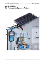
PV Photovoltaic Systems Trainer
AD 4
– MI 3399
255
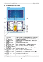
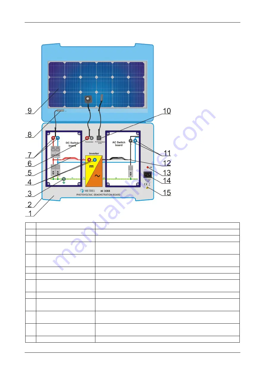
2 Front panel description
1
Front panel
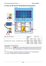
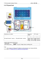
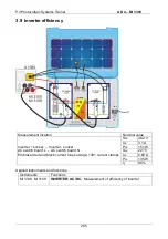
Presents typical components required in PV power utility.
2
Case
Plastic case of PV demonstration board with handle.
3
PE connection
For testing purposes only!
4
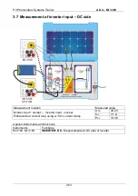
Inverter d.c. input
voltage
Sockets for measurement of inverter d.c. input voltage
(from PV array).
5
Inverter d.c. input
current
For applying d.c. current clamps.
6
Pyranometer output
Output for demonstration of irradiance measurement.
7
PV array output
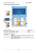
Output representing PV array I/U characteristics.
8
Connection to metallic
construction
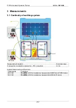
Intended for continuity measurement of grounding system.
9
Case cover with label
Label representing PV panel.
10 Temperature probe
output
Output representing PV array temperature.
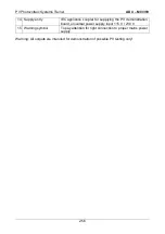
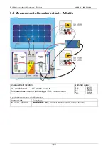
11 Inverter a.c. output
voltage
Sockets for measurement of inverter output a.c. voltage.
12 Inverter a.c. output
current
For applying a.c. current clamps.
13 Supply indicator
Indicates proper supply of the PV demonstration board.
Summary of Contents for MI 3399
Page 27: ...Electrical Installation Safety Trainer AD 1 MI 3399 27...
Page 46: ...Electrical Installation Safety Trainer AD 1 MI 3399 46 3 Exit settings...
Page 74: ...Electrical Installation Safety Trainer AD 1 MI 3399 74...
Page 197: ...Power and Voltage Quality Trainer AD 2 MI 3399 197 Figure 4 89 Transient Chart view...
Page 204: ...PAT Appliances Machines Safety Trainer AD 3 MI 3399 204...
Page 249: ...PV Photovoltaic Systems Trainer AD 4 MI 3399 249...
Page 250: ...PV Photovoltaic Systems Trainer AD 4 MI 3399 250 AD 4 MI 3399 PV Photovoltaic Systems Trainer...

