Power and Voltage Quality Trainer
AD 2
– MI 3399
184
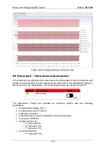
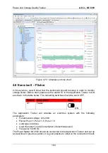
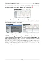
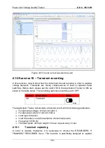
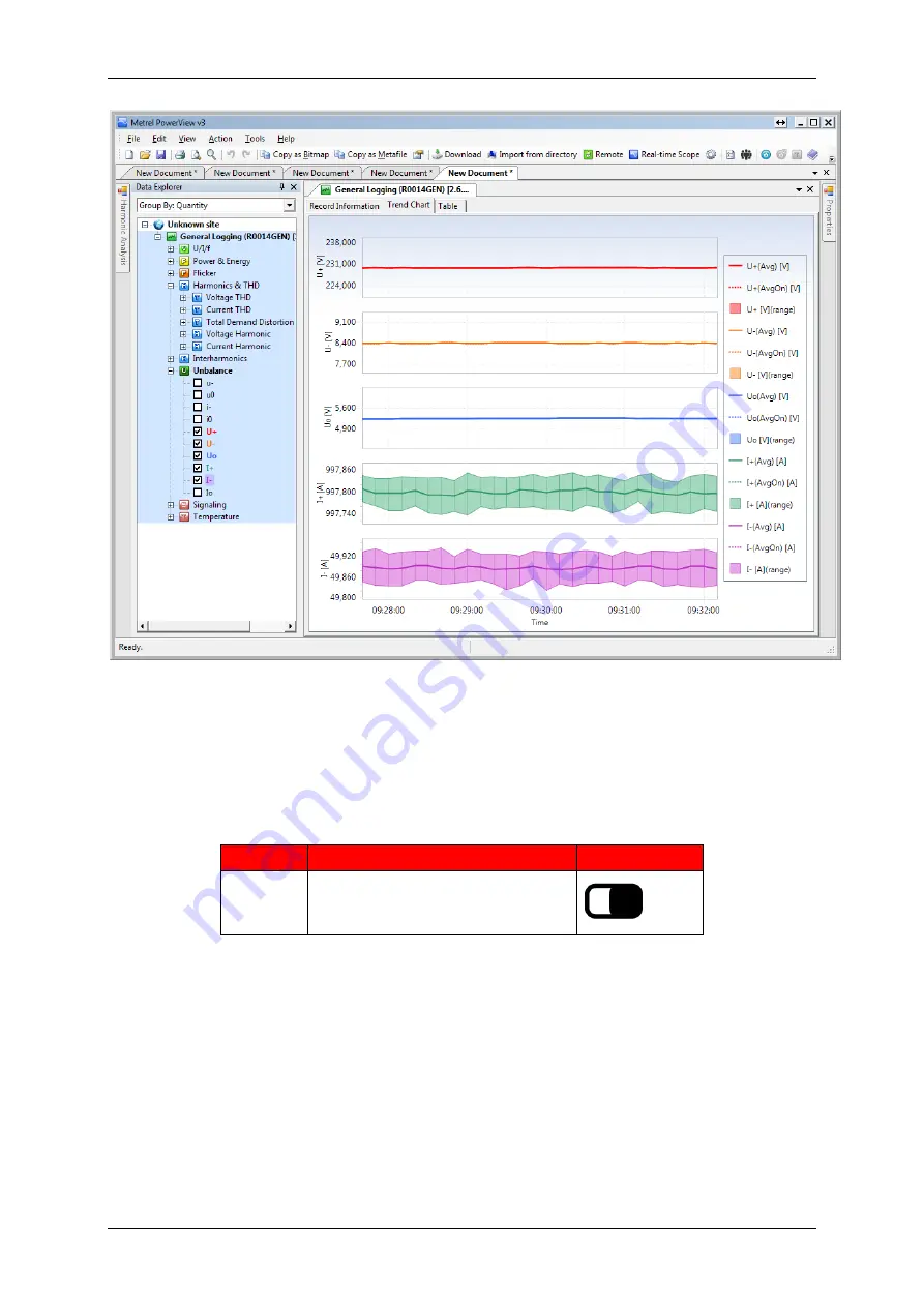
Figure 4-70: Unbalance in time chart
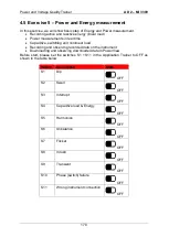
4.8 Exercise 8
– Flicker
In this exercise, we will show how the instrument should be setup in order to monitor
voltage flicker. Before start, please set the switch S7 in the Application Trainer to ON
as shown in the table below. The remaining switches should be set to OFF.
Switch
Description
State
S7
Flicker
ON
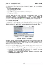
The Application Trainer will simulate an electrical system with the following
parameters:
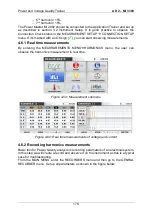
Fundamental voltage: U1=230V
Flicker Pst
U1
=1, Pst
U1
=1.5, Pst
U1
=1.8
Load type: Inductive
Load character: Load (Consumption of electrical power)
Frequency: 50/60 Hz
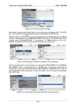
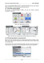
The Power Master MI 2892 should be connected to the Application Trainer and set up
as described in previous section. It is good practice to observe the Connection Check
Summary of Contents for MI 3399
Page 27: ...Electrical Installation Safety Trainer AD 1 MI 3399 27...
Page 46: ...Electrical Installation Safety Trainer AD 1 MI 3399 46 3 Exit settings...
Page 74: ...Electrical Installation Safety Trainer AD 1 MI 3399 74...
Page 197: ...Power and Voltage Quality Trainer AD 2 MI 3399 197 Figure 4 89 Transient Chart view...
Page 204: ...PAT Appliances Machines Safety Trainer AD 3 MI 3399 204...
Page 249: ...PV Photovoltaic Systems Trainer AD 4 MI 3399 249...
Page 250: ...PV Photovoltaic Systems Trainer AD 4 MI 3399 250 AD 4 MI 3399 PV Photovoltaic Systems Trainer...

