Electrical Installation Safety Trainer
AD 1 - MI 3399
115
For the second measurement the S probe should be placed at the same distance d2 on
the contrary side regarding to the H probe. Connections E, probes H and S should again
form an equilateral triangle. The difference between both measurements shall not exceed
10%. If a difference in excess of 10% occurs, distance d2 should be proportionally
increased and both measurements repeated. A simple solution is only to exchange test
probes S and H (can be done at the instrument side). The final result is an average of two
or more partial results.
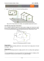
It is advisable for the measurement to be repeated at different placements of test probes.
The tes
t probes shall be placed in the opposite direction from tested electrode (180° or
at least 90°).
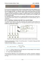
2.8.1.5 Earthing resistance test with two current clamps
This measurement system is used when measuring earth resistances of grounding rods,
cables etc., under- earth connections etc. The measuring method needs a closed loop to
be able to generate test currents.
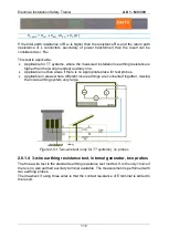
Figure 2-56: Total earthing resistance measurement with two current clamps
The driver clamp injects a voltage in the earthing system. The injected voltage generates
a test current in the loop.
Individual earthing resistance is measured as:
𝑅
𝐸2
+ (𝑅
𝐸1
|| 𝑅
𝐸3
||𝑅
𝐸4
… ) =
U
𝑔𝑒𝑛𝑒𝑟𝑎𝑡𝑜𝑟
1
𝑁
I
𝑐𝑙𝑎𝑚𝑝
[Ω]
U
generator
– Internal voltage source of test instrument, driving voltage for driver clamps.
I
clamp
– Current through sense clamps.
N
– Driver clamp transformation ratio.
If the total Earth Resistance of the electrodes R
E1
, R
E3
and R
E4
connected in parallel is
much lower than the resistance of tested electrode R
E2
, then the result can be considered
as
R
E21
.
Summary of Contents for MI 3399
Page 27: ...Electrical Installation Safety Trainer AD 1 MI 3399 27...
Page 46: ...Electrical Installation Safety Trainer AD 1 MI 3399 46 3 Exit settings...
Page 74: ...Electrical Installation Safety Trainer AD 1 MI 3399 74...
Page 197: ...Power and Voltage Quality Trainer AD 2 MI 3399 197 Figure 4 89 Transient Chart view...
Page 204: ...PAT Appliances Machines Safety Trainer AD 3 MI 3399 204...
Page 249: ...PV Photovoltaic Systems Trainer AD 4 MI 3399 249...
Page 250: ...PV Photovoltaic Systems Trainer AD 4 MI 3399 250 AD 4 MI 3399 PV Photovoltaic Systems Trainer...


