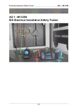
Electrical Installation Safety Trainer
AD 1 - MI 3399
32
Figure 2-5: Short circuit current between Line and Neutral....................................... 50
Figure 2-6: Short circuit current between two Phase conductors .............................. 51
Figure 2-7: Topology in a 1-phase TN system on the supply side ............................ 52
Figure 2-8: Topology in a 3-phase TN system on the outlet side .............................. 55
Figure 2-9: Simulated error on a 3-phase TN or TT system ..................................... 58
Figure 2-10: Chart reference for fault loop impedance measurements
Figure 2-11: Chart reference for fault loop impedance measurements
in Application Trainer’s switchboard with cables on the
in the Application Trainer with the schuko commander
Figure 2-16: Loop impedance measurement in a RCD protected system ................ 66
Figure 2-17: Topology in a 1-phase TN system on the supply side .......................... 66
Figure 2-18: Topology in a 1-phase TN system on the circuit side ........................... 69
Figure 2-19: Topology in a 3-phase TN system on the circuit side ........................... 70
Figure 2-20: Simulated error on PE conductor in a 1-phase TN system ................... 72
Figure 2-22: Chart reference for line impedance measurements .............................. 75
Figure 2-23: Chart reference for fault loop impedance measurements
24: RCD measurement in Application Trainer’s switchboard with cables on
Figure 2-26: RCD measurement in an IT earthing system........................................ 76
Figure 2-27: RCD measurement in a 1-phase TT system ........................................ 78
and IMD in an IT system .............................................. 84
Figure 2-32: Chart reference for insulation resistance measurements ..................... 90
Figure 2-33: Insulation resistance measurement at the switchboard
Figure 2-34: Insulation resistance measurement at the switchboard
Insulation test performed on switchboard and outlet
............................ 92
simulated error between phase and PE conductors ..................... 94
simulated error between phase and neutral conductors ............... 96
simulated error between phase conductors in an IT system ......... 98
Figure 2-39: Insulation resistance measurement at the varistor ............................. 100
simulated error on the varistor cabling ........................................ 101
Figure 2-41: Chart reference for continuity measurements .................................... 102
Figure 2-42: Continuity measurement between MPE and socket ........................... 102
Figure 2-43: Continuity measurement between switchboard and socket ................ 103
...................................................................... 104
Summary of Contents for MI 3399
Page 27: ...Electrical Installation Safety Trainer AD 1 MI 3399 27...
Page 46: ...Electrical Installation Safety Trainer AD 1 MI 3399 46 3 Exit settings...
Page 74: ...Electrical Installation Safety Trainer AD 1 MI 3399 74...
Page 197: ...Power and Voltage Quality Trainer AD 2 MI 3399 197 Figure 4 89 Transient Chart view...
Page 204: ...PAT Appliances Machines Safety Trainer AD 3 MI 3399 204...
Page 249: ...PV Photovoltaic Systems Trainer AD 4 MI 3399 249...
Page 250: ...PV Photovoltaic Systems Trainer AD 4 MI 3399 250 AD 4 MI 3399 PV Photovoltaic Systems Trainer...

