Electrical Installation Safety Trainer
AD 1 - MI 3399
105
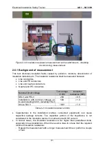
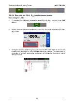
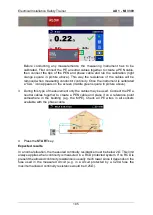
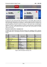
Before conducting any measurements, the measuring instrument has to be
calibrated. First connect the PE a neutral cables together to create a PEN cable,
then connect the tips of the PEN and phase cable and run the calibration (right
orange square in picture above). This way the resistance of the cables will be
removed when measuring conductor continuity. Once the instrument is calibrated
a “CAL” icon appears on the screen (middle green square in picture above).
3
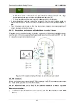
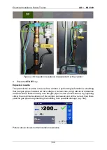
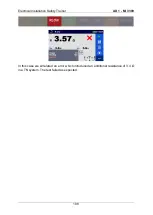
During this type of measurement only the cables may be used. Connect the PE a
neutral cables together to create a PEN cable and place it on a reference point
somewhere in the building (e.g. the MPE). Check all PE wires in all sockets
available with the phase cable.
4
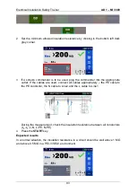
Press the
START
key.
Expected results
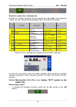
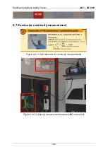
In a normal situation, the measured continuity resistance must be below 2
Ω. This limit
always applies when continuity is measured in a RCD protected system. If no RCD is
present the allowed continuity resistance is usually much lower since it depends on the
fuse used in the measured circuit (e.g. in a circuit protected by a C20A fuse the
maximum allowed continuity resistance would be 0,25
Ω).
Summary of Contents for MI 3399
Page 27: ...Electrical Installation Safety Trainer AD 1 MI 3399 27...
Page 46: ...Electrical Installation Safety Trainer AD 1 MI 3399 46 3 Exit settings...
Page 74: ...Electrical Installation Safety Trainer AD 1 MI 3399 74...
Page 197: ...Power and Voltage Quality Trainer AD 2 MI 3399 197 Figure 4 89 Transient Chart view...
Page 204: ...PAT Appliances Machines Safety Trainer AD 3 MI 3399 204...
Page 249: ...PV Photovoltaic Systems Trainer AD 4 MI 3399 249...
Page 250: ...PV Photovoltaic Systems Trainer AD 4 MI 3399 250 AD 4 MI 3399 PV Photovoltaic Systems Trainer...

