Electrical Installation Safety Trainer
AD 1 - MI 3399
111
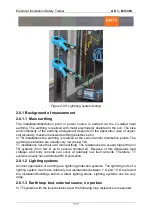
Figure 2-50: Lightning system testing
2.8.1 Background of measurement
2.8.1.1 Main earthing
The installation/distribution point or power source is earthed via the so-called main
earthing. The earthing is realized with metal electrode(s) depleted in the soil. The size
and complexity of the earthing arrangement depends on the application (size of object,
soil resistivity, maximum allowed earthing resistance etc.).
In TN installations the earthing is realized at the source and/or distribution points. The
earthing resistances are usually very low (below 1Ω).
TT installations have their own main earthing. The resistances are usually higher than in
TN systems (from few Ω up to several hundred Ω). Because of this dangerous fault
voltages and body currents can occur at relatively low fault currents. Therefore, TT
systems usually have additional RCD protection.
2.8.1.2 Lighting systems
Another application of earthing are lightning protection systems. The lightning rods of a
lighting system must have relatively low resistances (between 1 Ω and 10 Ω to prevent
the installation/buildings before a direct lighting struck. Lighting systems can be very
large.
2.8.1.3 Earth loop test, external source, no probes
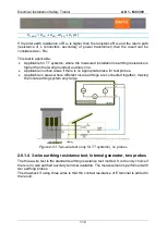
In TT systems with the loop resistance test the following loop resistance is measured:
Summary of Contents for MI 3399
Page 27: ...Electrical Installation Safety Trainer AD 1 MI 3399 27...
Page 46: ...Electrical Installation Safety Trainer AD 1 MI 3399 46 3 Exit settings...
Page 74: ...Electrical Installation Safety Trainer AD 1 MI 3399 74...
Page 197: ...Power and Voltage Quality Trainer AD 2 MI 3399 197 Figure 4 89 Transient Chart view...
Page 204: ...PAT Appliances Machines Safety Trainer AD 3 MI 3399 204...
Page 249: ...PV Photovoltaic Systems Trainer AD 4 MI 3399 249...
Page 250: ...PV Photovoltaic Systems Trainer AD 4 MI 3399 250 AD 4 MI 3399 PV Photovoltaic Systems Trainer...

