Electrical Safety and Quality ApplicationTrainer - Introduction
MI 3399
16
Use the test outlets on MI 3399 walls for test purpose only and not for
supplying different loads (radio, cooker, lamp etc.) because the components
inside the board (wiring, switches, contacts, resistors etc.) are dimensioned
for test purpose only.
To supply additional loads or instruments use the F0/1 outlet. This outlet is
connected in parallel to mains and not through electronic circuits.
Do not short accessible contacts at one-phase or three-phase outlets.
4.2.1 Connection to a 1-phase outlet
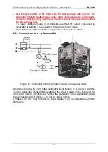
Figure 4-1: Connection of the Application Trainer to one-phase outlet.
After connecting the MI 3399 to the wall outlet check if lights L1, L2 and L3 are ON.
Turn the Application Trainer ON by switching the circuit breaker on the bottom of the
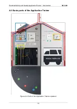
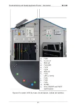
error switch panel (4 in Figure 4-4: Parts of the Application Trainer explained.). When
the switch is turned ON, lights L1, L2 and L3 should light up.
If lights L1, L2 and L3 do not light up, check chapter 4.2.3 Error handling for further
information.
Summary of Contents for MI 3399
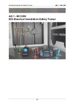
Page 27: ...Electrical Installation Safety Trainer AD 1 MI 3399 27...
Page 46: ...Electrical Installation Safety Trainer AD 1 MI 3399 46 3 Exit settings...
Page 74: ...Electrical Installation Safety Trainer AD 1 MI 3399 74...
Page 197: ...Power and Voltage Quality Trainer AD 2 MI 3399 197 Figure 4 89 Transient Chart view...
Page 204: ...PAT Appliances Machines Safety Trainer AD 3 MI 3399 204...
Page 249: ...PV Photovoltaic Systems Trainer AD 4 MI 3399 249...
Page 250: ...PV Photovoltaic Systems Trainer AD 4 MI 3399 250 AD 4 MI 3399 PV Photovoltaic Systems Trainer...

