Power and Voltage Quality Trainer
AD 2
– MI 3399
183
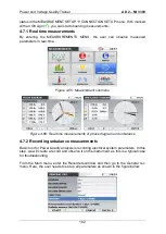
Figure 4-67: General record settings
The instrument is now prepared for recording electrical system parameters, generated
by the Application Trainer. Please start the recorder by pressing the
F1 (“START”) key.
The recorder can be stopped anytime, by pressing the F1 (STOP) key.
While recording is active
, the user can evaluate all recording parameters in TREND
screens, which appear in each MEASUREMENTS submenu. Figure below show
voltage trend (MEASUREMENT
Phase Diagram
TREND (press 2 x key F4).
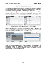
Figure 4-68: Showing 3
rd
harmonics trend on the instrument
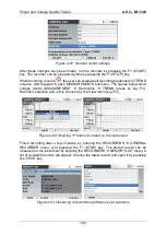
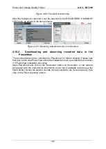
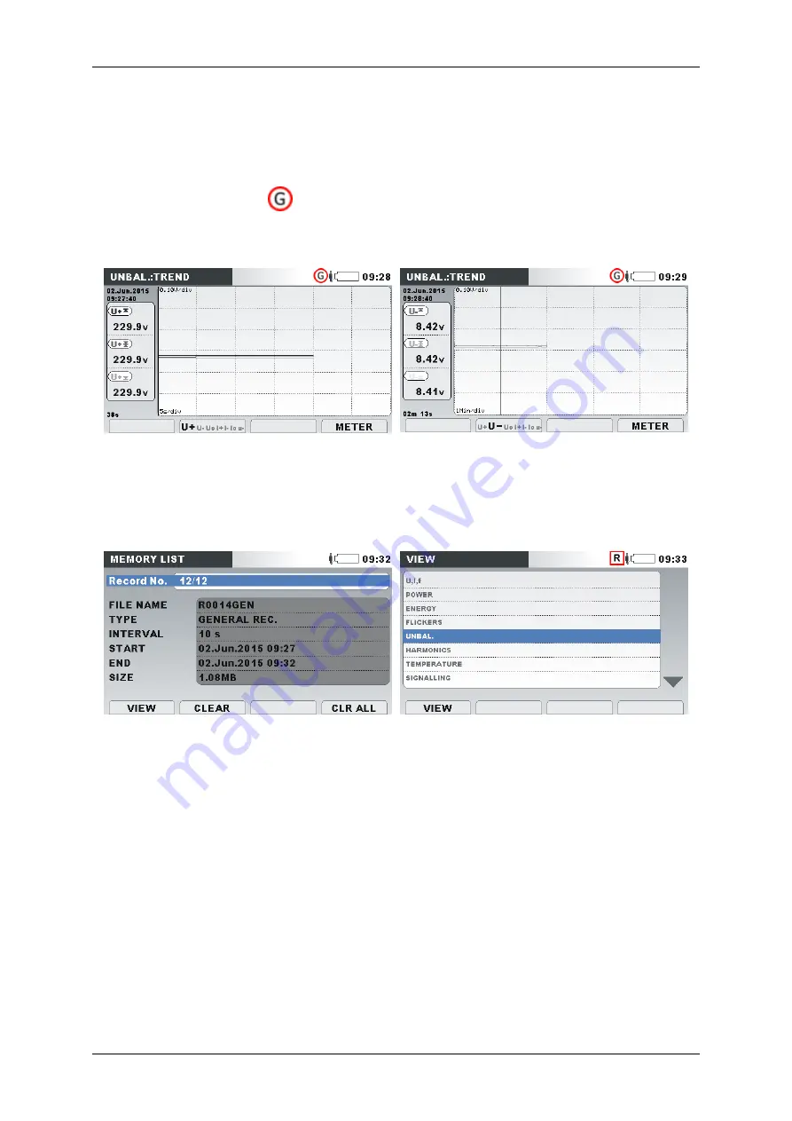
After few minutes record can be finished. Enter into RECORDERS
MEMORY LIST
menu. A list of available records will appear. Choose the latest record and open it by
pressing the
“VIEW” key. Select UNBAL to get unbalance data.
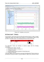
Figure 4-69: Observing records through Memory List submenu
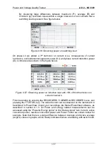
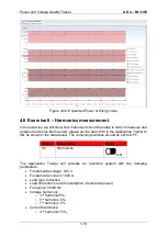
Power View provides several options to observe unbalances. All measurements can
be accessed through the
“Unbalance” node from the “Data Explorer”. Each
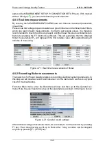
measurement may be presented in either chart or table presentation. Unbalance
screen example is shown in the figure below.
Summary of Contents for MI 3399
Page 27: ...Electrical Installation Safety Trainer AD 1 MI 3399 27...
Page 46: ...Electrical Installation Safety Trainer AD 1 MI 3399 46 3 Exit settings...
Page 74: ...Electrical Installation Safety Trainer AD 1 MI 3399 74...
Page 197: ...Power and Voltage Quality Trainer AD 2 MI 3399 197 Figure 4 89 Transient Chart view...
Page 204: ...PAT Appliances Machines Safety Trainer AD 3 MI 3399 204...
Page 249: ...PV Photovoltaic Systems Trainer AD 4 MI 3399 249...
Page 250: ...PV Photovoltaic Systems Trainer AD 4 MI 3399 250 AD 4 MI 3399 PV Photovoltaic Systems Trainer...

