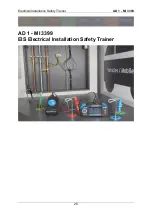
Electrical Installation Safety Trainer
AD 1 - MI 3399
34
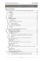
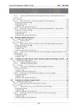
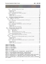
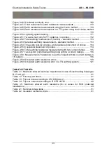
1 Basic theory about LV Electrical Installations
Safety and Measurements
Basic theory needed for successful completion of exercises is described in this chapter.
For a more detailed theoretical explanation, please see the Metrel’s Handbook
Guide
for testing and verification of low voltage installations
.
For a more detailed explanation on how to navigate to a specific device setting, please
refer to the appropriate instruction manual of the device used.
1.1 TN system
A TN system is earthed at the power source and/or distribution points. Exposed
conductive parts are connected (earthed) to the points via the PE or PEN conductor.
PEN conductor serves as supply and protective conductor at the same time. All line
conductors are fuse protected.
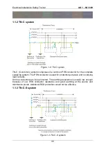
1.1.1 TN-S system
Figure 1-1: TN-S system
In TN-S (S=separated) systems the PE and N (if applied) conductors are separated.
The PE conductor serves for protection purposes only.
All line conductors are fuse protected. The system can contain additional RCD
protection. The earthing resistance is usually low enough because of low PE conductor
resistance and good earthing at the source and distribution points.
Summary of Contents for MI 3399
Page 27: ...Electrical Installation Safety Trainer AD 1 MI 3399 27...
Page 46: ...Electrical Installation Safety Trainer AD 1 MI 3399 46 3 Exit settings...
Page 74: ...Electrical Installation Safety Trainer AD 1 MI 3399 74...
Page 197: ...Power and Voltage Quality Trainer AD 2 MI 3399 197 Figure 4 89 Transient Chart view...
Page 204: ...PAT Appliances Machines Safety Trainer AD 3 MI 3399 204...
Page 249: ...PV Photovoltaic Systems Trainer AD 4 MI 3399 249...
Page 250: ...PV Photovoltaic Systems Trainer AD 4 MI 3399 250 AD 4 MI 3399 PV Photovoltaic Systems Trainer...

