Electrical Installation Safety Trainer
AD 1 - MI 3399
118
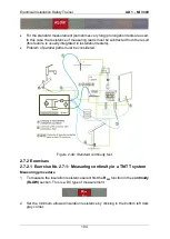
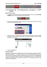
If measuring earth resistance in a TT earthing system, the probes may be replaced with
the shuko commander since all measurements may be done via the outlets.
4
Press the
START
key.
Expected results
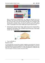
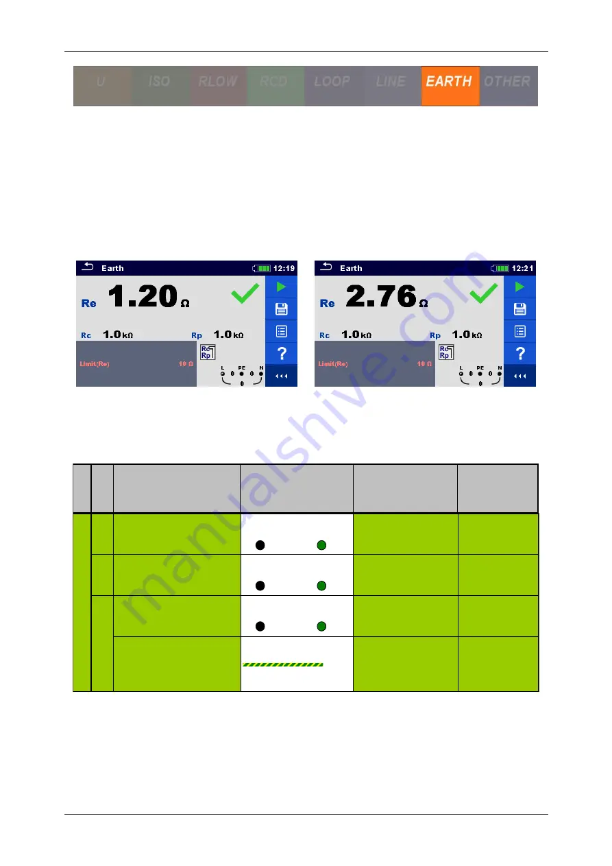
Expected earth resistance result is below 10
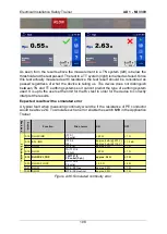
Ω. As may be observed from the figure below
the result varies whether a TN or TT earthing system is used. The latter usually has 2~3
Ω higher result as it also measures the resistance of the connected transformer.
Expected results with a simulated error
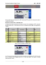
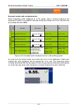
When measuring earth resistance in a TT system with a 3-wire method in the Application
Trainer it is possible to simulate grounding errors
S23
and
S24
.
Figure 2-59: Simulated earth resistance errors
E
xer
ci
ses
S
w
itch
Function
Site of error
ON
OFF
S23 R
E
(classic method 3w)
Basic grounding in TT
approx. 3.3 Ω
approx. 2.6 Ω
S23
+
S24
R
E
(classic method 3w)
Basic grounding in TT
approx. 9.8 Ω
approx. 2.6 Ω
R
E
(classic method 3w)
Basic grounding in TT
approx. 4.8 Ω
approx. 2.6 Ω
R
E
(2 - clamps method)
Basic grounding in TN
(on Main PE wire)
Lightning rod 1
Lightning rod 2
approx. 10 Ω
approx. 22 Ω
approx. 10 Ω
approx. 3.6 Ω
approx. 5 Ω
approx. 10 Ω
E
a
rt
h
R
e
s
is
ta
n
c
e
R
E
S24
Summary of Contents for MI 3399
Page 27: ...Electrical Installation Safety Trainer AD 1 MI 3399 27...
Page 46: ...Electrical Installation Safety Trainer AD 1 MI 3399 46 3 Exit settings...
Page 74: ...Electrical Installation Safety Trainer AD 1 MI 3399 74...
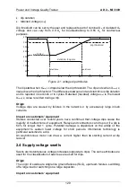
Page 197: ...Power and Voltage Quality Trainer AD 2 MI 3399 197 Figure 4 89 Transient Chart view...
Page 204: ...PAT Appliances Machines Safety Trainer AD 3 MI 3399 204...
Page 249: ...PV Photovoltaic Systems Trainer AD 4 MI 3399 249...
Page 250: ...PV Photovoltaic Systems Trainer AD 4 MI 3399 250 AD 4 MI 3399 PV Photovoltaic Systems Trainer...

