4
150209
PARTS IDENTIFICATION/FUNCTION
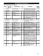
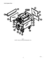
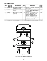
C836 Exploded View (See Figure 1.)
ITEM
TAYLOR
PART NO.
DESCRIPTION
QTY.
FUNCTION
WARR.
CLASS
1
074110
Panel-Side Left
1
Provides access to internal com-
ponents for service and cleaning.
103
2
024298
Screw-10-32 X 3/8
39
Secures the panel to the frame.
000
3
X74126
Panel A.-Side Left
(Upper)
1
Provides access to internal com-
ponents for service and cleaning.
103
4
083119
Panel-Back Service
(Upper)
1
Provides access to internal com-
ponents for service and cleaning.
103
5
078479
Panel-Back (Lower)
1
Provides access to internal com-
ponents for service and cleaning.
Has a two speed fan connector
built into the panel.
103
6
X78330-SER
Kit A.-Grease Shield
1
Prevents grease migration.
103
6a
078329
Fastener-Snap
8
Fastens grease shields to rear
shroud of grill.
000
6b
078285
Shield-Grease
4
Prevents grease migration.
000
7
X74127
Panel A.-Side Right
(Upper)
1
Provides access to internal com-
ponents for service and cleaning.
103
8
074111
Panel-Side Right
(Lower)
1
Provides access to internal com-
ponents for service and cleaning.
103
9
078377
Caster-5” 7-5/8 Stem
2
Allows grill mobility.
103
10
073240
Caster-Grill 5” Swivel
w/Lock
2
Prevents grill movement.
103
11
X72491-SER
Control-Display
1
Controls all functions of the grill.
103
12
075288
Guard-Lense
1
Protects the Standby button from
being accidentally activated.
103
13
076989-WP
Switch-Rocker-DPST
10A (Fan Interlock)
1
Activates power to the grill and the
exhaust fans.
103
14
076012
Button-Operator-Black
(Standby)
1
Activates the cook cycle, keeps
the upper platen in the closed po-
sition, and displays the message
“STANDBY” on the control. When
pressed twice within five seconds,
the upper platen will automatically
lower into the Standby position.
000
15
076011
Button-Operator-Red
(Raise)
1
Cancels the Standby mode, raises
the upper platen, and deactivates
the Cook cycle.
000
16
072472
Handle-Platen
1
The handle sits solidly on the
lower cook surface when the
platen is lowered.
103
Summary of Contents for C836
Page 2: ......
Page 7: ...5 150209 C836 Exploded View Figure 1 2015 Carrier Commercial Refrigeration Inc ...
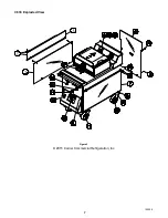
Page 9: ...7 150209 C838 Exploded View Figure 2 2015 Carrier Commercial Refrigeration Inc ...
Page 64: ...Rev 2 15 C836 C838 WIRING DIAGRAM 083305 75 ...
Page 65: ......
Page 66: ......
Page 67: ......
Page 68: ...073530 M ...

