6.0 TENSION CONTROL
www.maxcessintl.com
MAGPOWR Spyder-Plus-S1 Tension Control
MI 850A351 1 C
Page 14 of 68
6.1 ELECTRICAL CONNECTIONS
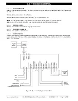
Figure 5 shows the simplest and minimal connections required for the basic Spyder load cell tension control
system. They are:
24 VDC power
Earth ground
One or two MAGPOWR load cells
RUN/STOP switch using the Spyder internal logic supply
E-Stop jumper between Term.10 and Term.11 (This is supplied by default from the factory)
Potentiometer (1K to 10K ohm) for tension setpoint. Alternately, Setpoint Tension can be set using the
Ethernetport. Choose the Setpoint Source from the Configure menu.
Output to clutch or brake amplifier, current-to-pressure transducer, motor controller, etc.
Route power wiring away from sensor and control wiring. Run all wiring in shielded cable, except for the 24 VDC
power which may be twisted pair. Connect cable shields to the terminals provided. Maximum shield length and
maximum length of wires outside of the shield is 1.5 inches (38 mm).
The load cell connections and signal inputs and outputs are Earth ground referenced. The power input circuit is not
isolated, since the negative lead of the 24 VDC power input is Earth ground referenced.
See Figure 9 for complete connections. See Figure 8 for connecting two MAGPOWR load cells. Other load cells
may also be used; contact Fife customer service for details.
6.2 SOFTWARE CONFIGURATION FOR LOAD CELL SYSTEM
Refer to the Load Cell screen flowchart at the end of this manual for a navigation aid.
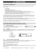
6.2.1 OPERATOR LOOP MENU
This section describes all the screens in the Operator Loop menu. All
screens are display only except for Percent Taper.
6.2.1.1
TENSION
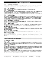
This screen shows the actual measured tension in numeric and bar graph form. The bar graph shows measured
tension and is scaled to the maximum tension set during calibration of the load cells. The lower left character
displays the status of the Spyder.
E
H
S
A
S
M
OFF
= E-Stop
= Hold
= Start
= Automatic (Run)
= Stop
= Manual mode
= Tension OFF
6.2.1.2
SETPOINT TENSION OR CORE TENSION
Setpoint Tension (or Core Tension with taper) is set by the voltage on Term.16 (Setpoint Source = Analog) or via
the Ethernet port (Setpoint Source = Ethernet). Setpoint Source is set in the Configure menu.
6.2.1.2.1
SETPOINT TENSION (No taper tension)
Display only.
6.2.1.2.2
CORE TENSION (With taper tension)
Display only. This is the setpoint at core diameter only. At other diameters the setpoint is less than the core setpoint
if Taper Percent > 0.
Summary of Contents for MAGPOWR Spyder-Plus-S1
Page 2: ......


