11.0
SCREEN DEFINITIONS, ALPHABETICAL LIST
www.maxcessintl.com
MAGPOWR Spyder-Plus-S1 Tension Control
MI 850A351 1 C
Page 51 of 68
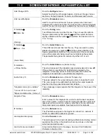
Hold Change With
From the
Configure
menu.
Selects how hold level changes happen. Hold level change choices
are None, Output, Diameter, Tension, and Diameter and Tension.
Hold Level Multiplier
From the
Parameters
menu.
Used for Load Cell and Dancer Torque systems when hold level
changes with output is selected. The output of the control during hold
mode is the last running output multiplied by the Hold Level Multiplier.
If Unstable
Stable Pxx
(Tuning)
From the
Tuning
menu.
Two different screens look like this one. They are used to optimize
the given parameter by first pressing
until the system becomes
slightly unstable and then press
to stabilize. See Section 6.4.2 or
7.5.2, Tuning.
If Unstable
Done Pxx
(Quick Stab)
From the
Quick Stab
menu.
Three different screens look like this one. They are used to quickly
stabilize the system by pressing
until the system stabilizes. The
Spyder automatically switches to the next screen if the most stable
value of the parameter being tuned has not stabilized the system.
The parameter being tuned is indicated by either a
P
, or an
I
.
If Unstable
If Now Stable
From the
Quick Stab
menu (dancers only).
The screen appears if the integrator was originally
on
and is now
off
.
If the system is now stable, the instability was caused by the
integrator. A following series of screens explains this before the
integrator is turned back on to stabilize the integrator.
Inertia Comp %
From the
Parameters
menu. (Dancer Torque only)
The value added to the output during stop time to help stop the roll.
This value needs to be calibrated by entering the output needed to
stop the roll at the present diameter and tension.
"Integrator mode (I) is unstable"
"I is now off. Turn on to tune"
"Expect unstable when I turns on"
These message screens explain that the integrator is the cause of the
instability.
Integrator Time
From the
Parameters
menu.
Enter a value for the integrator time, which sets the basic response
time of the system. A value that is too high will make the system less
responsive to tension errors, while a value that is too low will make
the system quick but unstable. See Section 9.6.6 for defaults.
IP Address
From the
Network
menu.
The IP address assigned to the Spyder to connect to a network. If
DHCP is enabled this address is ignored.
Load applied wrong way
From
Cal Sensors
menu
The load applied to the load cell (during calibration and during normal
operation) should be in the direction shown by arrows on the load
cells. See load cell manual.
Load cells are overloaded.
A load cell calibration error message.
See Load Cell Calibration
Problems
in Section 10.4.
Summary of Contents for MAGPOWR Spyder-Plus-S1
Page 2: ......

