CALIBRATE TENSION THROUGH FIELDBUS
www.maxcessintl.com
DLCA NET-S1
MI 850A374 1 A
Page 58 of 67
If the calibration is successful, then
Tension Polarity
(0x216
and 0x223) will automatically be set to show positive tension
when force is applied in the direction of the calibration force.
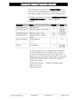
The following parameters in the group
Configuration Tension 1
or
Configuration Tension 2
are set by the calibration
procedure:
Parameter
Name
Default
Range
0x208 and 0x218
ADC PGA Gain 1
5
{0, 7}
0x209 and 0x219
Display Tension 1A Zero Offset
0
{-0xFFFFFF,
0xFFFFFF}
0x20E and 0x21B
Display Tension 1 Scale
623
{0, 999000}
0x20F and 0x21C
Display Tension 1 Number
Format
0x10
{0, 0xFF}
0x216 and 0x223
Tension Polarity
0 = -1
1 = +1
1
{0, 1}
0x25B
Tension Ratio
1.0
{-FLT_MAX,
FLT_MAX}
The above parameter set is determined by the DLCA NET-
S1 during calibration. Do not modify the value of these
parameters. The parameters above, along with those in the
following list, can be read from a DLCA NET-S1, and can be
sent to the same DLCA NET-S1 to restore a corrupted
calibration if needed.
Decimal Point Position
Maximum Tension
Calibration Tension
Load Cell Excitation Voltage


