OPERATION
www.maxcessintl.com
DLCA NET-S1
MI 850A374 1 A
Page 22 of 67
4.5
LED indicators
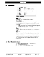
Power
Channel 1 (Tension Zone 1)
Channel 2 (Tension Zone 2)
Tension Sum (not used)
Alarm 1
Alarm 2
Error
Figure 6. LED indicators
Power (Green)
When power is on the Power indicator will be on.
Tension display (Green)
The LEDs indicate which channel or sum is being displayed.
While displaying tension, press [Enter] to cycle the display through
the channels.
-
For two tension zones, the display switches between Channels 1
and 2 (Tension Zones 1 and 2, respectively).
Alarms (Red)
There are two alarm indicators showing whether each alarm is active
or not.
Error (Red)
The Error indicator will show voltage errors or a load cell check error.
One flash per second indicates a load cell check error. Two flashes
per second indicates there is a voltage error on either the load cell
excitation, internal 12V or internal 5V supplies. The load cell check
only runs during power-up. The voltage monitoring check runs
continuously.
4.6
Load cell excitation voltage
The load cell excitation voltage can be either 5V or 7.5V.
Use 7.5V with MAGPOWR load cells.
Use 5V or 7.5V if using non-MAGPOWR load cell

