Installing a data link
25
be disturbed or flexed when the rear cover plate is removed for service. All cable entry/exit
holes that are not used must be sealed with blanking plugs.
Connection pinouts
XLR connection
XLR connectors are suitable if DMX cable is used for the data link.
XLR pin numbers are normally marked on connectors. Connectors must be wired using
the standard XLR DMX pin-out:
• Pin 1: Cable shield
• Pin 2: DMX Data 1 - (cold)
• Pin 3: DMX Data 1 + (hot)
Pins 4 and 5 on 5-pin XLR connectors are available for Data 2 connections in DMX 512-A
or similar systems. They must be wired as follows:
• Pin 4: DMX Data 2 - (cold)
• Pin 5: DMX Data 2 + (hot)
To avoid ground/earth loop interference, ensure that the DMX cable shield does not come
into contact with the shell or body of XLR connectors.
RJ-45 connection
RJ-45 connectors are suitable if CAT 5 cable is used for the data link.
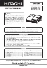
RJ-45 cable connector pins are numbered from the left looking at the face of the
connector with the locking clip on top (see Figure 11). Connectors must be wired using the
standard RJ-45 DMX pin-out:
• Pin 1 (WHITE/orange): DMX hot (+)
• Pin 2 (ORANGE/white): DMX cold (-)
• Pins 7 (WHITE/brown) and 8 (BROWN/white):
Common
Pins 3 and 6 are available for Data 2 connections in
DMX 512-A or similar systems. They must be wired as
follows:
• Pin 3 (WHITE/green): Available for Data 2 hot (+)
• Pin 6 (GREEN/white): Available for Data 2 cold (-)
Pins 4 and 5 are not used in currently available lighting control systems but can be wired
as follows:
• Pin 4 (BLUE/white): Not used
• Pin 5 (WHITE/blue): Not used
Connecting the link
To build a data link:
1. If the luminaire has been in use, allow it to cool for at least 20 minutes.
2. Connect the data cable to a DMX output socket on the DMX controller and route it to
the first luminaire on the link.
3. If the rear cover plate is not already open, remove it as described in "
3.1.4:
Connections compartment access"
on page 19
Pin 1
Pin 8
Figure 11: RJ-45 cable
connector pins
Summary of Contents for Exterior 1200
Page 1: ...user manual Exterior 1200 Image Projector ...
Page 3: ...3 Section 1 Safety ...
Page 9: ...Section 2 Introduction ...
Page 12: ...12 Exterior 1200 Image Projector user manual ...
Page 13: ...Introduction to the Exterior 1200 Image Projector 13 Section 3 Installation ...
Page 27: ...Installing a data link 27 Section 4 General ...
Page 32: ...32 Exterior 1200 Image Projector user manual ...
Page 33: ...General 33 Section 5 Settings and configuration ...
Page 39: ...Luminaire settings 39 Section 6 Stand alone operation ...
Page 50: ...50 Exterior 1200 Image Projector user manual ...
Page 51: ...Stand alone playback 51 Section 7 DMX control ...
Page 57: ...DMX controller operation 57 Section 8 Service and accessories ...
Page 78: ...78 Exterior 1200 Image Projector user manual ...
Page 79: ...Accessories 79 Section 9 Reference ...
Page 90: ...Notes ...
Page 91: ......