Installing AC power
21
The luminaire must be configured to accept the local AC power frequency and voltage by
connecting the free ends of two jumper leads. The fixed end of each lead sits in an orange
terminal. The free end of each lead must be connected to the appropriate terminal on the
terminal block. Terminals are labelled.
The terminals are spring-loaded, and a lead can be inserted and released by pressing on
its terminal tab with a flat-head screwdriver.
To configure the luminaire for local AC power:
1. Make sure that the luminaire is isolated from AC power and cannot be accidentally
connected throughout the procedure.
2. Open the connections compartment as described in "
3.1.4: Connections compartment
access"
on page 19.
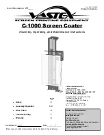
3. See Figure 8. Connect the free end of the
frequency setting jumper lead (in the
section marked
Hz setting
) to the
terminal labeled with the local AC power
frequency.
4. Connect the free end of the voltage
setting jumper lead (in the section marked
Volt setting
) to the terminal labeled with
the local AC power voltage.
3 . 2 . 2 C o n n e c t i n g t o A C p o w e r
Power cable must enter the luminaire through an M20 x 1.5 cable gland that accepts 8 -
13 mm (0.32 - 0.5 in.) external diameter cables. A gland is supplied with the luminaire.
The cable gland must be replaced if the power cable diameter is not within this range (see
"
8.4.2: Cable glands"
on page 61).
One of two cable entry points can be used: either on the cover plate at the rear of the
luminaire, or through the bottom of the connections/power compartment. Using the bottom
of the connections/power compartment is recommended, as cables installed here will not
be disturbed or flexed when the rear cover plate is removed for service. All cable entry/exit
holes that are not used must be sealed with blanking plugs.
1. Make sure that the power cable is isolated from power and that power cannot be
applied accidentally. If the luminaire has been in use, allow it to cool for at least 20
minutes.
2. If necessary, remove the rear cover plate as described in "
3.1.4: Connections
compartment access"
on page 19
3. Check that the jumper leads are correctly connected to match the local AC power
voltage and frequency (see "
3.2.1: Configuring for local AC power"
on page 20).
50
60
277
250
240
230
220
208
200
Hz setting
Volt setting
Figure 8: Frequency and voltage
settings
Summary of Contents for Exterior 1200
Page 1: ...user manual Exterior 1200 Image Projector ...
Page 3: ...3 Section 1 Safety ...
Page 9: ...Section 2 Introduction ...
Page 12: ...12 Exterior 1200 Image Projector user manual ...
Page 13: ...Introduction to the Exterior 1200 Image Projector 13 Section 3 Installation ...
Page 27: ...Installing a data link 27 Section 4 General ...
Page 32: ...32 Exterior 1200 Image Projector user manual ...
Page 33: ...General 33 Section 5 Settings and configuration ...
Page 39: ...Luminaire settings 39 Section 6 Stand alone operation ...
Page 50: ...50 Exterior 1200 Image Projector user manual ...
Page 51: ...Stand alone playback 51 Section 7 DMX control ...
Page 57: ...DMX controller operation 57 Section 8 Service and accessories ...
Page 78: ...78 Exterior 1200 Image Projector user manual ...
Page 79: ...Accessories 79 Section 9 Reference ...
Page 90: ...Notes ...
Page 91: ......