Operating Instructions
Functional Manual
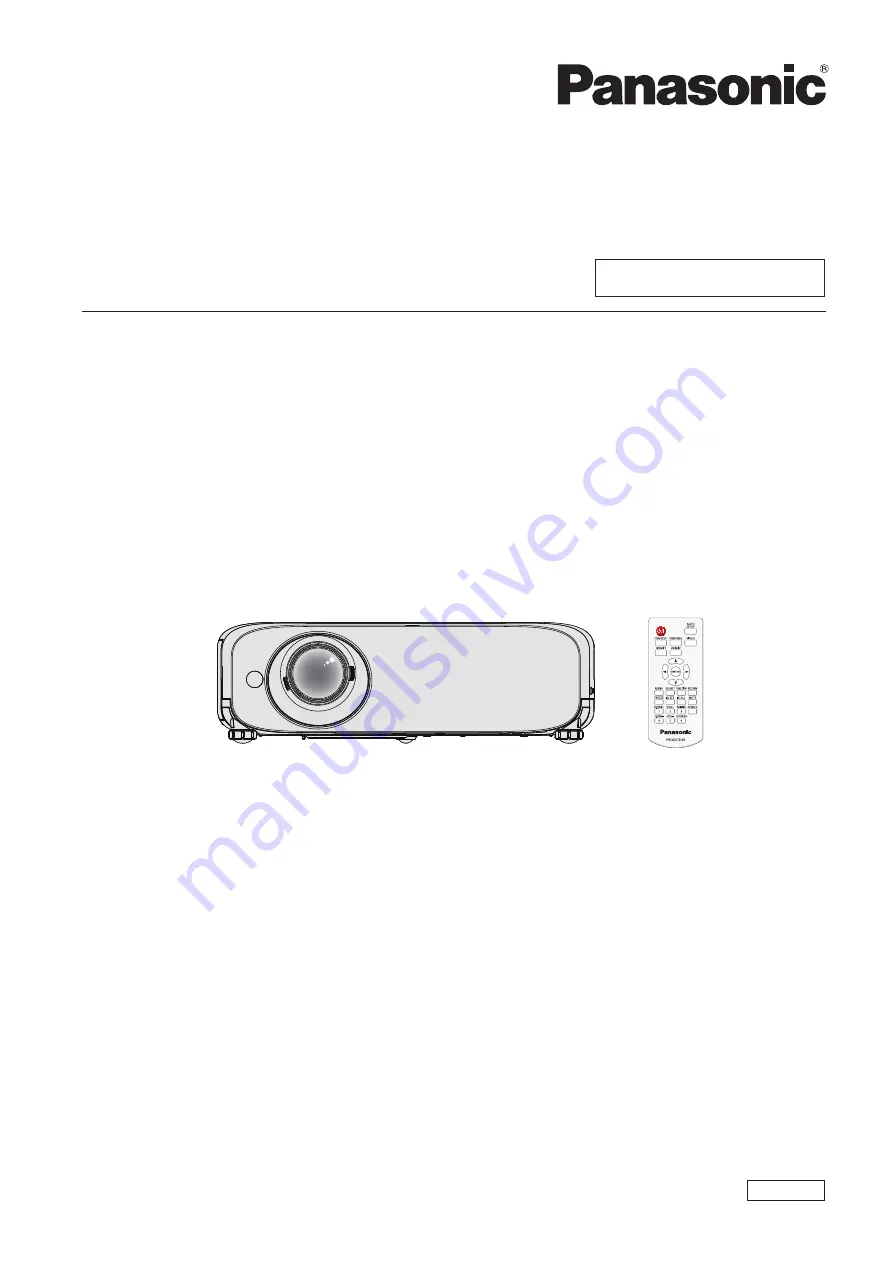
LCD Projector
Commercial Use
Thank you for purchasing this Panasonic Product.
■
Before operating this product, please read the instructions carefully, and save this manual
for future use.
■
Before using your projector, be sure to read “Read this first!” (
Æ
pages 2 to 8).
Model No.
PT-VZ570
PT-VW530
PT-VX600
ENGLISH
TQBJ0721