P. 1
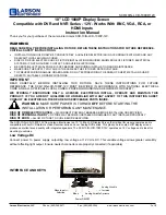
KIT CONTENTS:
770L 1280L
ITEM A Side Panel
x1 x1
ITEM B Front Panel
x1 x1
ITEM C Side Panel
x1 x1
ITEM D 5mm x 20mm Chipboard Screw
x29 x33
ITEM E M10 x 120mm Ground Fixing Bolt x6 x6
ITEM F Support Leg
x2 x2
ITEM G Side Skirting (optional)
x2 x2
ITEM H Front Skirting (optional)
x1 x1
ITEM I Repair Washer M5 x 25mm S/S
x16
x20
(optional)
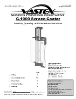
Assembled
Three Sided
Screen
(770 L)
AND MODUS ARE TRADEMARKS OF GLASDON GROUP AND ITS SUBSIDIARIES IN
THE U.K. AND OTHER COUNTRIES.
Replacement components are available direct from GLASDON.
GLASDON cannot be held responsible for claims arising from incorrect installation, unauthorised modifications or misuse of
the product.
Issue 2
December 2011
C000/0406
© Copyright 2011
Glasdon U.K. Ltd reserves the right to alter specifications without prior notice.
Preston New Road
BLACKPOOL
Lancashire FY4 4UL
Tel: 01253 600410
Fax: 01253 792558
E-mail: [email protected]
Web: www.glasdon.com
TM
FRONT
SIDE
VISAGE SCREEN SYSTEM - THREE SIDED (FLAT PACK)
ASSEMBLY & FIXING INSTRUCTION LEAFLET
TM
A
B
C
D
E
F
G
H
I
TOOLS REQUIRED:
13mm Spanner
x1
Hand Drill with Pozi Drill Bit
x1
10mm x 150mm Masonry Drill Bit x1
Rubber Mallet
x1
Hammer x1
17mm Spanner
x2
6mm Allen Key
x1
NOTE: Ensure that all relevant personnel read the points listed below and that a copy is passed on to staff involved
with the installation. Please also refer to the ‘Manual Handling Operations Regulations 1992’ during the
handling of the product and materials used for installation. The total weight of this product is 53kg (770L) and
65kg (1280L).
NOTE: Some fixings apply to the optional skirting
so there may be less fixings than stated.
We recommend that a risk assessment is undertaken to identify an appropriate location for your waste
collection and recycling units. In order to reduce risk, some organisations decide to place the units a
minimum
of 5 metres
away from buildings. Any potential risk can be further reduced by maintaining a regime of regularly
emptying the unit.