


General information
1-45
7510
Go Back
Previous
Next
Names
and functions of components
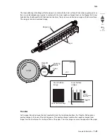
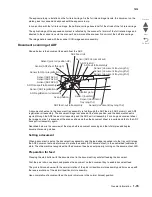
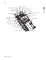
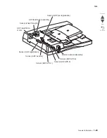
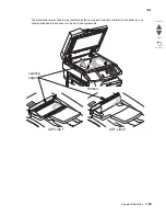
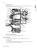
The sections below describe the functions of main components of the scanner.
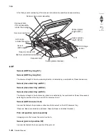
Scanner unit assembly
Sensor (platen length APS 1)
Sensor (platen length APS 2)
The document length in the slow scanning direction is detected by a combination of the two reflector sensors.
Switch (platen interlock)
A switch that detects whether the ADF is open and determines the timing of platen document size detection.
Sensor (ADF angle)
A sensor that detects the angle at which the ADF opens and determines the timing of platen document size
detection.
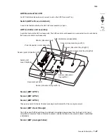
Scanner drive motor assembly
A stepping motor that drives the full rate carriage and the half rate carriage.
Sensor (scanner HP)
A sensor that detects the HP position of the full rate carriage.
The rear portion of the full rate carriage frame functions as an actuator that shields the sensor (scanner HP) for
detection.
Scanner exposure lamp
A xenon lamp to which the document is exposed.
Exposure lamp PS card assembly
A card that switches on/off the exposure lamp according to the signal from the scanner controller card assembly.
Lens assembly
A kit that consists of a lens used to read the document and a CCD image sensor used to photoelectrically
convert the image data read from the document.
Scanner controller card assembly
A card that controls the scanner section.
Scanner cooling fan
Summary of Contents for X945E
Page 20: ...xx Service Manual 7510 Go Back Previous Next ...
Page 25: ...Notices and safety information xxv 7510 Go Back Previous Next ...
Page 26: ...xxvi Service Manual 7510 Go Back Previous Next ...
Page 32: ...xxxii Service Manual 7510 Go Back Previous Next ...
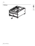
Page 88: ...1 56 Service Manual 7510 Go Back Previous Next TTM theory ...
Page 97: ...General information 1 65 7510 Go Back Previous Next 3TM theory ...
Page 104: ...1 72 Service Manual 7510 Go Back Previous Next 1TM theory ...
Page 111: ...General information 1 79 7510 Go Back Previous Next Duplex ...
Page 432: ...3 52 Service Manual 7510 Go Back Previous Next ...
Page 475: ...Repair information 4 43 7510 Go Back Previous Next E F ...
Page 483: ...Repair information 4 51 7510 Go Back Previous Next Connectors A ...
Page 623: ...Repair information 4 191 7510 Go Back Previous Next ...
Page 653: ...Repair information 4 221 7510 Go Back Previous Next ...
Page 714: ...4 282 Service Manual 7510 Go Back Previous Next ...
Page 715: ...Connector locations 5 1 7510 Go Back Previous Next 5 Connector locations Locations ...
Page 720: ...5 6 Service Manual 7510 Go Back Previous Next Printhead Polygon mirror motor ...
Page 725: ...Connector locations 5 11 7510 Go Back Previous Next ...
Page 726: ...5 12 Service Manual 7510 Go Back Previous Next ...
Page 729: ...Connector locations 5 15 7510 Go Back Previous Next Switch media size Switch TTM media size ...
Page 765: ...Parts catalog 7 31 7510 Go Back Previous Next Assembly 29 Electrical 1 3 5 9 2 10 6 4 8 1 7 ...
Page 770: ...7 36 MFP Service Manual 7510 Go Back Previous Next Assembly 32 Electrical 4 2 1 4 3 5 7 6 8 9 ...
Page 797: ...Parts catalog 7 63 7510 Go Back Previous Next Assembly 50 1TM feed unit assembly 4 3 5 4 1 2 ...
Page 802: ...7 68 MFP Service Manual 7510 Go Back Previous Next Assembly 53 1TM drive and electrical ...
Page 804: ...7 70 MFP Service Manual 7510 Go Back Previous Next Assembly 54 3TM covers 3 5 2 4 1 ...
Page 812: ...7 78 MFP Service Manual 7510 Go Back Previous Next Assembly 58 3TM drive and electrical ...
Page 815: ...Parts catalog 7 81 7510 Go Back Previous Next Assembly 60 TTM media trays 3 5 4 3 7 2 6 8 1 ...
Page 824: ...7 90 MFP Service Manual 7510 Go Back Previous Next Assembly 67 TTM drive and electrical ...
Page 828: ...7 94 MFP Service Manual 7510 Go Back Previous Next ...
Page 836: ...I 8 Service Manual 7510 Go Back Previous Next ...
Page 844: ...I 16 Service Manual 7510 Go Back Previous Next ...


