
Repair information
4-101
7510
Go Back
Previous
Next
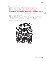
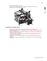
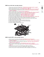
13. Remove the 24V LVPS card bracket assembly. See
“24V LVPS card bracket assembly removal” on
page 4-95
.
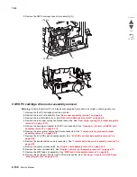
14. Remove the CMYK transfer HVPS card assembly. See
“CMYK transfer HVPS card assembly removal”
on page 4-103
15. Remove the K developer transport drive motor assembly. See
“K developer / transport drive motor
assembly removal” on page 4-106
.
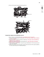
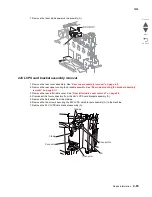
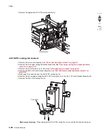
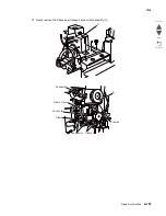
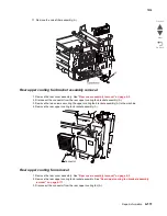
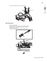
16. Remove the two connectors from the CMYK PC cartridge drive motor assembly (A).
17. Release the hook securing the access cover (B) to the machine.
18. Remove the access cover (B).
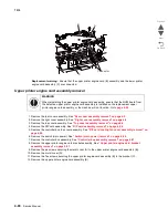
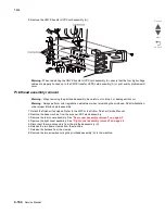
19. Remove the two screws securing the socket (C) to the machine.
20. Detach the socket (C) from the machine.
Note:
The lower left screw can be accessed through the hole in the frame where the socket (B) was
detached in step 7.
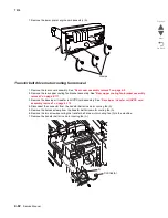
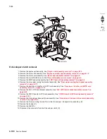
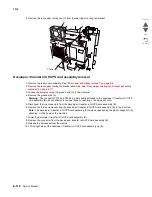
21. Remove the eight screws securing the CMY PC cartridge drive motor assembly (A) to the machine.
22. When removing the CMYK PC cartridge drive motor assembly (A), ensure none of the harnesses become
damaged.
23. Remove the CMYK PC cartridge drive motor assembly (A).
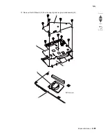
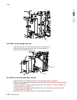
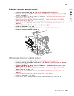
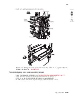
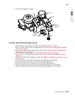
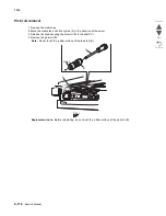
Fuser cooling fan removal
1. Remove the rear cover assembly. See
“Rear cover assembly removal” on page 4-5
.
2. Remove the right cover assembly. See
“Right cover assembly removal” on page 4-4
.
3. Remove the top cover assembly. See
“Top cover assembly removal” on page 4-4
or
“Rear cover
assembly removal” on page 4-5
.
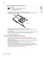
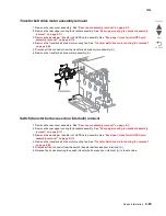
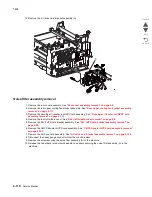
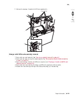
4. Disconnect the connector from the fuser cooling fan (A).
5. Remove the harness from the clamps.
6. Lift the fuser cooling fan (A).
Connector
A
Connector
B
C
Screwdriver
access hole
Summary of Contents for X945E
Page 20: ...xx Service Manual 7510 Go Back Previous Next ...
Page 25: ...Notices and safety information xxv 7510 Go Back Previous Next ...
Page 26: ...xxvi Service Manual 7510 Go Back Previous Next ...
Page 32: ...xxxii Service Manual 7510 Go Back Previous Next ...
Page 88: ...1 56 Service Manual 7510 Go Back Previous Next TTM theory ...
Page 97: ...General information 1 65 7510 Go Back Previous Next 3TM theory ...
Page 104: ...1 72 Service Manual 7510 Go Back Previous Next 1TM theory ...
Page 111: ...General information 1 79 7510 Go Back Previous Next Duplex ...
Page 432: ...3 52 Service Manual 7510 Go Back Previous Next ...
Page 475: ...Repair information 4 43 7510 Go Back Previous Next E F ...
Page 483: ...Repair information 4 51 7510 Go Back Previous Next Connectors A ...
Page 623: ...Repair information 4 191 7510 Go Back Previous Next ...
Page 653: ...Repair information 4 221 7510 Go Back Previous Next ...
Page 714: ...4 282 Service Manual 7510 Go Back Previous Next ...
Page 715: ...Connector locations 5 1 7510 Go Back Previous Next 5 Connector locations Locations ...
Page 720: ...5 6 Service Manual 7510 Go Back Previous Next Printhead Polygon mirror motor ...
Page 725: ...Connector locations 5 11 7510 Go Back Previous Next ...
Page 726: ...5 12 Service Manual 7510 Go Back Previous Next ...
Page 729: ...Connector locations 5 15 7510 Go Back Previous Next Switch media size Switch TTM media size ...
Page 765: ...Parts catalog 7 31 7510 Go Back Previous Next Assembly 29 Electrical 1 3 5 9 2 10 6 4 8 1 7 ...
Page 770: ...7 36 MFP Service Manual 7510 Go Back Previous Next Assembly 32 Electrical 4 2 1 4 3 5 7 6 8 9 ...
Page 797: ...Parts catalog 7 63 7510 Go Back Previous Next Assembly 50 1TM feed unit assembly 4 3 5 4 1 2 ...
Page 802: ...7 68 MFP Service Manual 7510 Go Back Previous Next Assembly 53 1TM drive and electrical ...
Page 804: ...7 70 MFP Service Manual 7510 Go Back Previous Next Assembly 54 3TM covers 3 5 2 4 1 ...
Page 812: ...7 78 MFP Service Manual 7510 Go Back Previous Next Assembly 58 3TM drive and electrical ...
Page 815: ...Parts catalog 7 81 7510 Go Back Previous Next Assembly 60 TTM media trays 3 5 4 3 7 2 6 8 1 ...
Page 824: ...7 90 MFP Service Manual 7510 Go Back Previous Next Assembly 67 TTM drive and electrical ...
Page 828: ...7 94 MFP Service Manual 7510 Go Back Previous Next ...
Page 836: ...I 8 Service Manual 7510 Go Back Previous Next ...
Page 844: ...I 16 Service Manual 7510 Go Back Previous Next ...


