Diagnostic aids
3-11
7510
Go Back
Previous
Next
•
Single
—Feeds one sheet of media from the selected source.
•
Continuous
—Media continues feeding from the selected input source until
Stop
is
pressed.
Sensor Test (input tray)
This test is used to verify that a specific input tray’s sensors are working correctly.
To run the Input Tray Sensor Test:
1.
Touch
INPUT TRAY TESTS
from the Diagnostics Menu.
2.
Touch
Sensor Test
.
After selecting
Sensor Test
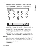
, the LCD displays each installed input source, one source per line. When you select
an input source, the LCD displays the selected input source in the header row, and then displays the name of
each of the source’s sensors below the header row, one to a line. You must select a specific sensor from this list
in order to view and toggle the sensor’s state. The table below indicates which sensors are available in each
input tray.
1
Feed-out Testing...
appears on the LCD with the sensor’s current state (Open or Closed).
2
Media out Testing...
appears on the LCD with the sensor’s current state (Open or Closed).
3
Media level Testing...
appears on the LCD with the sensor’s current state (Open or Closed).
4
Tray 1 present...
appears on the LCD with the sensor’s current state (Open or Closed).
After selecting a specific sensor, you can manually toggle the sensor between its two values (Open or Closed).
The LCD displays
Open
when the sensor is open, and
Closed
when the sensor is closed. If the wrong message
is displayed, then the sensor must be malfunctioning.
Press
Stop
to exit the test.
OUTPUT BIN TESTS
Feed Tests (output bins)
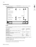
Use these tests to verify that media can be fed to a specific output bin. Media is fed from the default input source
to the selected output bin. No information is printed on the media fed to the output bin because the printhead is
not engaged during this test. These tests can use any media size or envelope supported by the printer.
To run the Feed Tests for the output bins:
1.
Touch
OUTPUT BIN TESTS
from the Diagnostics Menu.
2.
Touch
Feed Tests
.
3.
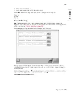
Touch the output bin you want the paper to exit into. The standard bin as well as any output option bin
installed on the printer is shown on the menu.
•
Standard Bin
•
Output Bin 1
4.
Touch either
Single
or
Continuous
.
•
Single
—Feeds one sheet of media from the selected source.
Input source
Sensors
Feed-out
1
Media out
2
Media level
3
Tray 1 present
4
Tray 1
Yes
Yes
Yes
Yes
Tray 2
Yes
Yes
Yes
Yes
Tray 3
Yes
Yes
Yes
Yes
Tray 4
Yes
Yes
Yes
Yes
MP Feeder
No
Yes
No
No
Summary of Contents for X945E
Page 20: ...xx Service Manual 7510 Go Back Previous Next ...
Page 25: ...Notices and safety information xxv 7510 Go Back Previous Next ...
Page 26: ...xxvi Service Manual 7510 Go Back Previous Next ...
Page 32: ...xxxii Service Manual 7510 Go Back Previous Next ...
Page 88: ...1 56 Service Manual 7510 Go Back Previous Next TTM theory ...
Page 97: ...General information 1 65 7510 Go Back Previous Next 3TM theory ...
Page 104: ...1 72 Service Manual 7510 Go Back Previous Next 1TM theory ...
Page 111: ...General information 1 79 7510 Go Back Previous Next Duplex ...
Page 432: ...3 52 Service Manual 7510 Go Back Previous Next ...
Page 475: ...Repair information 4 43 7510 Go Back Previous Next E F ...
Page 483: ...Repair information 4 51 7510 Go Back Previous Next Connectors A ...
Page 623: ...Repair information 4 191 7510 Go Back Previous Next ...
Page 653: ...Repair information 4 221 7510 Go Back Previous Next ...
Page 714: ...4 282 Service Manual 7510 Go Back Previous Next ...
Page 715: ...Connector locations 5 1 7510 Go Back Previous Next 5 Connector locations Locations ...
Page 720: ...5 6 Service Manual 7510 Go Back Previous Next Printhead Polygon mirror motor ...
Page 725: ...Connector locations 5 11 7510 Go Back Previous Next ...
Page 726: ...5 12 Service Manual 7510 Go Back Previous Next ...
Page 729: ...Connector locations 5 15 7510 Go Back Previous Next Switch media size Switch TTM media size ...
Page 765: ...Parts catalog 7 31 7510 Go Back Previous Next Assembly 29 Electrical 1 3 5 9 2 10 6 4 8 1 7 ...
Page 770: ...7 36 MFP Service Manual 7510 Go Back Previous Next Assembly 32 Electrical 4 2 1 4 3 5 7 6 8 9 ...
Page 797: ...Parts catalog 7 63 7510 Go Back Previous Next Assembly 50 1TM feed unit assembly 4 3 5 4 1 2 ...
Page 802: ...7 68 MFP Service Manual 7510 Go Back Previous Next Assembly 53 1TM drive and electrical ...
Page 804: ...7 70 MFP Service Manual 7510 Go Back Previous Next Assembly 54 3TM covers 3 5 2 4 1 ...
Page 812: ...7 78 MFP Service Manual 7510 Go Back Previous Next Assembly 58 3TM drive and electrical ...
Page 815: ...Parts catalog 7 81 7510 Go Back Previous Next Assembly 60 TTM media trays 3 5 4 3 7 2 6 8 1 ...
Page 824: ...7 90 MFP Service Manual 7510 Go Back Previous Next Assembly 67 TTM drive and electrical ...
Page 828: ...7 94 MFP Service Manual 7510 Go Back Previous Next ...
Page 836: ...I 8 Service Manual 7510 Go Back Previous Next ...
Page 844: ...I 16 Service Manual 7510 Go Back Previous Next ...

