
Diagnostic information
2-193
7510
Go Back
Previous
Next
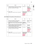
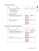
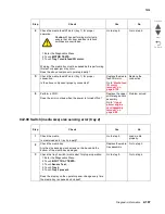
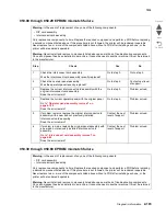
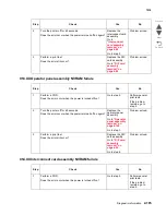
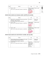
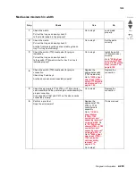
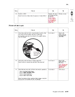
950.00 through 950.29 EPROM mismatch failure
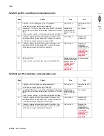
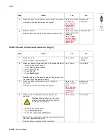
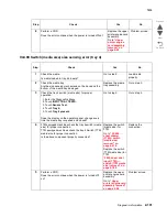
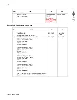
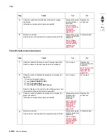
950.30 through 950.60 EPROM mismatch failure
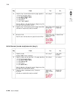
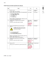
Warning:
In the event of replacement of any one of the following components:
• RIP card assembly
• Interconnect card assembly
Only replace one component at a time. Replace the required component, and perform a POR before replacing
a second component listed above. If this procedure is not followed, the printer will be rendered inoperable.
Never replace two or more of the components listed above without a POR after installing each one, or the
printer will be rendered inoperable.
Warning:
Never install and remove components listed above as a method of troubleshooting components.
Once a component has been installed in a machine, it cannot be used in another machine. It must be returned
to the manufacturer.
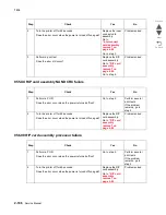
Step
Check
Yes
No
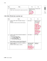
1
Check the interconnect card assembly.
Was the interconnect card assembly recently replaced?
Go to step 3.
Go to step 2.
2
Check the operator panel assembly.
Was the operator panel recently replaced?
Go to step 4.
Contact next level
of support.
3
Replace the current interconnect card assembly with the
original interconnect card assembly.
Does the error remain?
Go to step 5.
Problem solved.
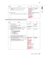
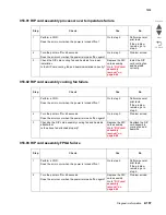
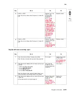
4
Replace the current operator panel with the original panel.
Go to
“Operator panel assembly removal” on
page 4-126
.
Does the error remain?
Go to step 6.
Problem solved.
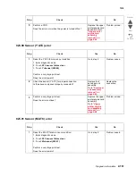
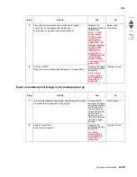
5
If problem remains, replace the original interconnect card
assembly with a new and not previously installed
interconnect card assembly.
Does the error remain?
Contact the next
level of support.
Problem solved.
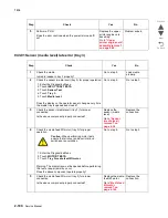
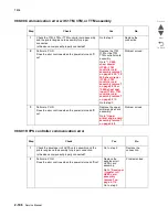
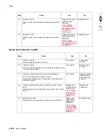
6
If problem remains, replace the original panel assembly with
a new and not previously installed interconnect card
assembly.
Go to
“Interconnect card assembly removal” on
page 4-86
.
Does the error remain?
Contact the next
level of support.
Problem solved.
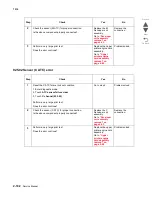
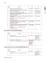
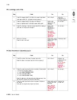
Warning:
In the event of replacement of any one of the following components:
• RIP card assembly
• Interconnect card assembly
Only replace one component at a time. Replace the required component, and perform a POR before replacing
a second component listed above. If this procedure is not followed, the printer will be rendered inoperable.
Never replace two or more of the components listed above without a POR after installing each one, or the
printer will be rendered inoperable.
Warning:
Never install and remove components listed above as a method of troubleshooting components.
Once a component has been installed in a machine, it cannot be used in another machine. It must be returned
to the manufacturer.
Summary of Contents for X945E
Page 20: ...xx Service Manual 7510 Go Back Previous Next ...
Page 25: ...Notices and safety information xxv 7510 Go Back Previous Next ...
Page 26: ...xxvi Service Manual 7510 Go Back Previous Next ...
Page 32: ...xxxii Service Manual 7510 Go Back Previous Next ...
Page 88: ...1 56 Service Manual 7510 Go Back Previous Next TTM theory ...
Page 97: ...General information 1 65 7510 Go Back Previous Next 3TM theory ...
Page 104: ...1 72 Service Manual 7510 Go Back Previous Next 1TM theory ...
Page 111: ...General information 1 79 7510 Go Back Previous Next Duplex ...
Page 432: ...3 52 Service Manual 7510 Go Back Previous Next ...
Page 475: ...Repair information 4 43 7510 Go Back Previous Next E F ...
Page 483: ...Repair information 4 51 7510 Go Back Previous Next Connectors A ...
Page 623: ...Repair information 4 191 7510 Go Back Previous Next ...
Page 653: ...Repair information 4 221 7510 Go Back Previous Next ...
Page 714: ...4 282 Service Manual 7510 Go Back Previous Next ...
Page 715: ...Connector locations 5 1 7510 Go Back Previous Next 5 Connector locations Locations ...
Page 720: ...5 6 Service Manual 7510 Go Back Previous Next Printhead Polygon mirror motor ...
Page 725: ...Connector locations 5 11 7510 Go Back Previous Next ...
Page 726: ...5 12 Service Manual 7510 Go Back Previous Next ...
Page 729: ...Connector locations 5 15 7510 Go Back Previous Next Switch media size Switch TTM media size ...
Page 765: ...Parts catalog 7 31 7510 Go Back Previous Next Assembly 29 Electrical 1 3 5 9 2 10 6 4 8 1 7 ...
Page 770: ...7 36 MFP Service Manual 7510 Go Back Previous Next Assembly 32 Electrical 4 2 1 4 3 5 7 6 8 9 ...
Page 797: ...Parts catalog 7 63 7510 Go Back Previous Next Assembly 50 1TM feed unit assembly 4 3 5 4 1 2 ...
Page 802: ...7 68 MFP Service Manual 7510 Go Back Previous Next Assembly 53 1TM drive and electrical ...
Page 804: ...7 70 MFP Service Manual 7510 Go Back Previous Next Assembly 54 3TM covers 3 5 2 4 1 ...
Page 812: ...7 78 MFP Service Manual 7510 Go Back Previous Next Assembly 58 3TM drive and electrical ...
Page 815: ...Parts catalog 7 81 7510 Go Back Previous Next Assembly 60 TTM media trays 3 5 4 3 7 2 6 8 1 ...
Page 824: ...7 90 MFP Service Manual 7510 Go Back Previous Next Assembly 67 TTM drive and electrical ...
Page 828: ...7 94 MFP Service Manual 7510 Go Back Previous Next ...
Page 836: ...I 8 Service Manual 7510 Go Back Previous Next ...
Page 844: ...I 16 Service Manual 7510 Go Back Previous Next ...


