


1-8
Service Manual
7510
Go Back
Previous
Next
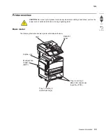
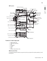
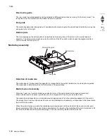
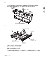
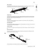
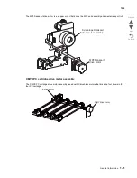
Rear media guide
The rear media tray guide assembly can be adjusted to different media sizes by moving it to the front or rear. The
rear guide come into contact with the media and hold it in position.
End guide
The media tray assembly is designed so it can adapt to the media length in the media feed direction by moving the
end guide to the left or right.
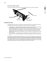
Bottom plate
The force pushing up the bottom plate is transmitted by the driving force of the motor on the media feed unit
assembly. The bottom plate is pushed up by the rotation of the lift up shaft, which causes the supplied media to
come in contact with the pick roll.
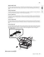
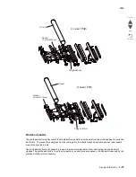
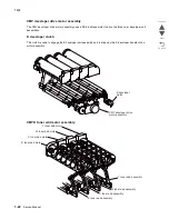
Media tray assembly
Detection of media size
The media size set for the media tray assembly is transmitted to the switch (media size) by moving these guides.
The media size is detected by the on/off information of these switches.
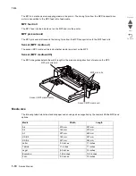
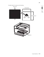
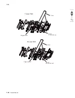
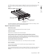
Media feed unit assembly
Since tray 1 and tray 2 are functionally equivalent in terms of the switch (media size), sensor (media out),
sensor (media level) and sensor (pre-feed), only the components of one tray are described here.
The media feed unit assembly is a mechanical unit supplying media from the media tray assembly to the printer.
The driving force, from the media feed lift motor on the media feed unit assembly, is transmitted to the three media
feed rolls to feed media.
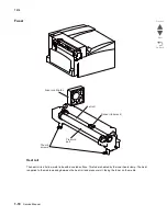
When the pick roll picks up media, the remaining media decreases, and the actuator of the sensor (media level)
lowers accordingly. When the sensor (media level) detects the lowering, the media feed lift motor is activated to lift
the lift up shaft and the bottom plate accordingly. Thus, the remaining media is ready to be fed.
Rear media guide
Bottom plate
End guide
Summary of Contents for X945E
Page 20: ...xx Service Manual 7510 Go Back Previous Next ...
Page 25: ...Notices and safety information xxv 7510 Go Back Previous Next ...
Page 26: ...xxvi Service Manual 7510 Go Back Previous Next ...
Page 32: ...xxxii Service Manual 7510 Go Back Previous Next ...
Page 88: ...1 56 Service Manual 7510 Go Back Previous Next TTM theory ...
Page 97: ...General information 1 65 7510 Go Back Previous Next 3TM theory ...
Page 104: ...1 72 Service Manual 7510 Go Back Previous Next 1TM theory ...
Page 111: ...General information 1 79 7510 Go Back Previous Next Duplex ...
Page 432: ...3 52 Service Manual 7510 Go Back Previous Next ...
Page 475: ...Repair information 4 43 7510 Go Back Previous Next E F ...
Page 483: ...Repair information 4 51 7510 Go Back Previous Next Connectors A ...
Page 623: ...Repair information 4 191 7510 Go Back Previous Next ...
Page 653: ...Repair information 4 221 7510 Go Back Previous Next ...
Page 714: ...4 282 Service Manual 7510 Go Back Previous Next ...
Page 715: ...Connector locations 5 1 7510 Go Back Previous Next 5 Connector locations Locations ...
Page 720: ...5 6 Service Manual 7510 Go Back Previous Next Printhead Polygon mirror motor ...
Page 725: ...Connector locations 5 11 7510 Go Back Previous Next ...
Page 726: ...5 12 Service Manual 7510 Go Back Previous Next ...
Page 729: ...Connector locations 5 15 7510 Go Back Previous Next Switch media size Switch TTM media size ...
Page 765: ...Parts catalog 7 31 7510 Go Back Previous Next Assembly 29 Electrical 1 3 5 9 2 10 6 4 8 1 7 ...
Page 770: ...7 36 MFP Service Manual 7510 Go Back Previous Next Assembly 32 Electrical 4 2 1 4 3 5 7 6 8 9 ...
Page 797: ...Parts catalog 7 63 7510 Go Back Previous Next Assembly 50 1TM feed unit assembly 4 3 5 4 1 2 ...
Page 802: ...7 68 MFP Service Manual 7510 Go Back Previous Next Assembly 53 1TM drive and electrical ...
Page 804: ...7 70 MFP Service Manual 7510 Go Back Previous Next Assembly 54 3TM covers 3 5 2 4 1 ...
Page 812: ...7 78 MFP Service Manual 7510 Go Back Previous Next Assembly 58 3TM drive and electrical ...
Page 815: ...Parts catalog 7 81 7510 Go Back Previous Next Assembly 60 TTM media trays 3 5 4 3 7 2 6 8 1 ...
Page 824: ...7 90 MFP Service Manual 7510 Go Back Previous Next Assembly 67 TTM drive and electrical ...
Page 828: ...7 94 MFP Service Manual 7510 Go Back Previous Next ...
Page 836: ...I 8 Service Manual 7510 Go Back Previous Next ...
Page 844: ...I 16 Service Manual 7510 Go Back Previous Next ...


