


Repair information
4-73
7510
Go Back
Previous
Next
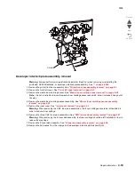
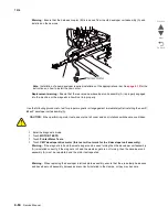
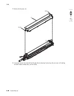
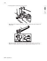
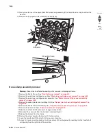
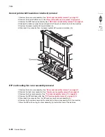
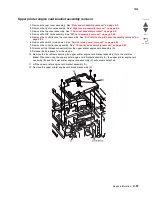
event that the PC unit assembly (C) becomes bound, it can be removed by twisting it in a clockwise
direction while pulling it from the machine.
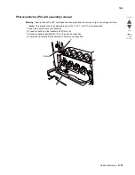
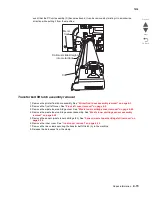
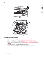
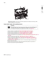
Transfer belt lift latch assembly removal
1. Remove the printer front door assembly. See
“Printer front door assembly removal” on page 4-3
.
2. Remove the front left cover. See
“Front left cover removal” on page 4-9
.
3. Remove the waste toner cartridge cover. See
“Waste toner cartridge cover removal” on page 4-49
.
4. Remove the waste toner cartridge sensor assembly. See
“Waste toner cartridge sensor assembly
removal” on page 4-49
.
5. Remove the sensor (waste toner cartridge full). See
“Sensor (waste toner cartridge full) removal” on
page 4-50
.
6. Remove the inner cover. See
“Inner cover removal” on page 4-53
.
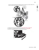
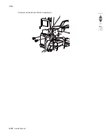
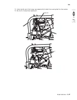
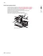
7. Remove the two screws securing the transfer belt lift latch (A) to the machine.
8. Release the harnesses from the clamp.
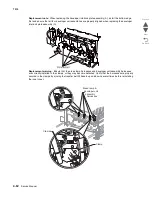
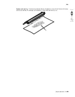
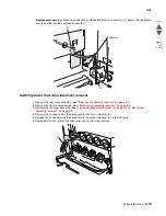
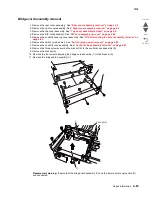
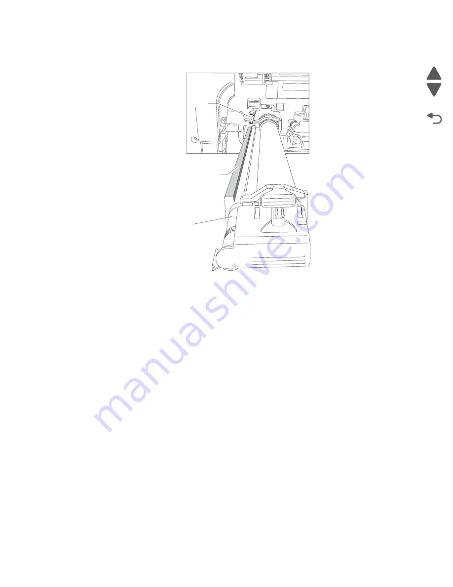
Metal
track
A
1
Rail must slide straight
into metal track
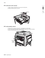
C
Summary of Contents for X945E
Page 20: ...xx Service Manual 7510 Go Back Previous Next ...
Page 25: ...Notices and safety information xxv 7510 Go Back Previous Next ...
Page 26: ...xxvi Service Manual 7510 Go Back Previous Next ...
Page 32: ...xxxii Service Manual 7510 Go Back Previous Next ...
Page 88: ...1 56 Service Manual 7510 Go Back Previous Next TTM theory ...
Page 97: ...General information 1 65 7510 Go Back Previous Next 3TM theory ...
Page 104: ...1 72 Service Manual 7510 Go Back Previous Next 1TM theory ...
Page 111: ...General information 1 79 7510 Go Back Previous Next Duplex ...
Page 432: ...3 52 Service Manual 7510 Go Back Previous Next ...
Page 475: ...Repair information 4 43 7510 Go Back Previous Next E F ...
Page 483: ...Repair information 4 51 7510 Go Back Previous Next Connectors A ...
Page 623: ...Repair information 4 191 7510 Go Back Previous Next ...
Page 653: ...Repair information 4 221 7510 Go Back Previous Next ...
Page 714: ...4 282 Service Manual 7510 Go Back Previous Next ...
Page 715: ...Connector locations 5 1 7510 Go Back Previous Next 5 Connector locations Locations ...
Page 720: ...5 6 Service Manual 7510 Go Back Previous Next Printhead Polygon mirror motor ...
Page 725: ...Connector locations 5 11 7510 Go Back Previous Next ...
Page 726: ...5 12 Service Manual 7510 Go Back Previous Next ...
Page 729: ...Connector locations 5 15 7510 Go Back Previous Next Switch media size Switch TTM media size ...
Page 765: ...Parts catalog 7 31 7510 Go Back Previous Next Assembly 29 Electrical 1 3 5 9 2 10 6 4 8 1 7 ...
Page 770: ...7 36 MFP Service Manual 7510 Go Back Previous Next Assembly 32 Electrical 4 2 1 4 3 5 7 6 8 9 ...
Page 797: ...Parts catalog 7 63 7510 Go Back Previous Next Assembly 50 1TM feed unit assembly 4 3 5 4 1 2 ...
Page 802: ...7 68 MFP Service Manual 7510 Go Back Previous Next Assembly 53 1TM drive and electrical ...
Page 804: ...7 70 MFP Service Manual 7510 Go Back Previous Next Assembly 54 3TM covers 3 5 2 4 1 ...
Page 812: ...7 78 MFP Service Manual 7510 Go Back Previous Next Assembly 58 3TM drive and electrical ...
Page 815: ...Parts catalog 7 81 7510 Go Back Previous Next Assembly 60 TTM media trays 3 5 4 3 7 2 6 8 1 ...
Page 824: ...7 90 MFP Service Manual 7510 Go Back Previous Next Assembly 67 TTM drive and electrical ...
Page 828: ...7 94 MFP Service Manual 7510 Go Back Previous Next ...
Page 836: ...I 8 Service Manual 7510 Go Back Previous Next ...
Page 844: ...I 16 Service Manual 7510 Go Back Previous Next ...


