3-42
Service Manual
7510
Go Back
Previous
Next
Format Fax Storage
This setting enables you to format the non-volatile storage used for storing faxes.
To change this setting:
1.
Touch
Format Fax Storage
from the Configuration Menu.
Note:
If an advanced password has been established, you must enter this password in order to change the
setting. If no advanced password exists, you can establish one by using the keyboard that appears on the LCD.
2.
Touch
Submit
to save the change.
3.
Touch
Back
to cancel and return to the Configuration Menu.
Formatting Fax Flash DO NOT POWER OFF
appears on the LCD while the format operation is active.
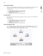
EVENT LOG (Configuration Menu)
This entry enables you to print a report that contains a limited set of the information that appears in the
Diagnostics version of the Event Log report. See
“EVENT LOG” on page 3-20
. The limited (Configuration) and
the full (Diagnostics) printed versions of this report display the same panel messages when they print and follow
the same layout guidelines.
To print the Event Log:
1.
Touch
EVENT LOG
from the Configuration Menu.
2.
Touch
Print Log
.
Touch
Back
to return to the Configuration Menu.
Note:
An event log printed from the Configuration Menu will not contain debug information or secondary codes
for 900 service errors. However, the event log printed from the Diagnostics Menu does include this information.
ADF Edge Erase
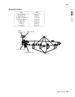
The ADF Edge Erase and FB Edge Erase settings specify, in millimeters, the size of a border around the
scanned image that will be erased. For copies, the printed page will have a 2 mm no-print border. The larger of
the 2 mm no-print border and the Edge Erase setting will be used in this situation.
To change this setting:
1.
Touch
ADF Edge Erase
from the Configuration Menu.
[setting's current value]
appears on the
touch-screen.
2.
Touch
to increase the value or
to decrease the value.
3.
Touch
Submit
to save the change.
4.
Touch
Back
to cancel and return to the Configuration Menu.
FB Edge Erase
The ADF Edge Erase and FB Edge Erase settings specify, in millimeters, the size of a border around the
scanned image that will be erased. For copies, the printed page will have a 2 mm no-print border. The larger of
the 2 mm no-print border and the Edge Erase setting will be used in this situation.
To change this setting:
1.
Touch
FB Edge Erase
from the Configuration Menu.
[setting's current value]
appears on the
touch-screen.
2.
Touch
to increase the value or
to decrease the value.
3.
Touch
Submit
to save the change.
4.
Touch
Back
to cancel and return to the Configuration Menu.
Summary of Contents for X945E
Page 20: ...xx Service Manual 7510 Go Back Previous Next ...
Page 25: ...Notices and safety information xxv 7510 Go Back Previous Next ...
Page 26: ...xxvi Service Manual 7510 Go Back Previous Next ...
Page 32: ...xxxii Service Manual 7510 Go Back Previous Next ...
Page 88: ...1 56 Service Manual 7510 Go Back Previous Next TTM theory ...
Page 97: ...General information 1 65 7510 Go Back Previous Next 3TM theory ...
Page 104: ...1 72 Service Manual 7510 Go Back Previous Next 1TM theory ...
Page 111: ...General information 1 79 7510 Go Back Previous Next Duplex ...
Page 432: ...3 52 Service Manual 7510 Go Back Previous Next ...
Page 475: ...Repair information 4 43 7510 Go Back Previous Next E F ...
Page 483: ...Repair information 4 51 7510 Go Back Previous Next Connectors A ...
Page 623: ...Repair information 4 191 7510 Go Back Previous Next ...
Page 653: ...Repair information 4 221 7510 Go Back Previous Next ...
Page 714: ...4 282 Service Manual 7510 Go Back Previous Next ...
Page 715: ...Connector locations 5 1 7510 Go Back Previous Next 5 Connector locations Locations ...
Page 720: ...5 6 Service Manual 7510 Go Back Previous Next Printhead Polygon mirror motor ...
Page 725: ...Connector locations 5 11 7510 Go Back Previous Next ...
Page 726: ...5 12 Service Manual 7510 Go Back Previous Next ...
Page 729: ...Connector locations 5 15 7510 Go Back Previous Next Switch media size Switch TTM media size ...
Page 765: ...Parts catalog 7 31 7510 Go Back Previous Next Assembly 29 Electrical 1 3 5 9 2 10 6 4 8 1 7 ...
Page 770: ...7 36 MFP Service Manual 7510 Go Back Previous Next Assembly 32 Electrical 4 2 1 4 3 5 7 6 8 9 ...
Page 797: ...Parts catalog 7 63 7510 Go Back Previous Next Assembly 50 1TM feed unit assembly 4 3 5 4 1 2 ...
Page 802: ...7 68 MFP Service Manual 7510 Go Back Previous Next Assembly 53 1TM drive and electrical ...
Page 804: ...7 70 MFP Service Manual 7510 Go Back Previous Next Assembly 54 3TM covers 3 5 2 4 1 ...
Page 812: ...7 78 MFP Service Manual 7510 Go Back Previous Next Assembly 58 3TM drive and electrical ...
Page 815: ...Parts catalog 7 81 7510 Go Back Previous Next Assembly 60 TTM media trays 3 5 4 3 7 2 6 8 1 ...
Page 824: ...7 90 MFP Service Manual 7510 Go Back Previous Next Assembly 67 TTM drive and electrical ...
Page 828: ...7 94 MFP Service Manual 7510 Go Back Previous Next ...
Page 836: ...I 8 Service Manual 7510 Go Back Previous Next ...
Page 844: ...I 16 Service Manual 7510 Go Back Previous Next ...

