


Repair information
4-143
7510
Go Back
Previous
Next
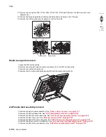
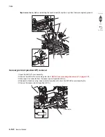
8. Remove the document tray assembly. See
“Document tray assembly removal” on page 4-144
.
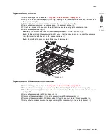
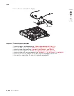
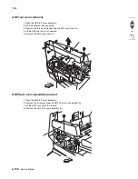
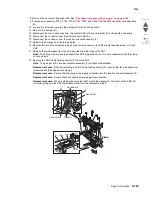
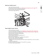
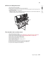
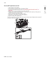
9. Disconnect connectors P754, P755, P758, P761, P785, and P786 from the ADF controller card assembly
(A).
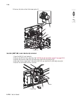
10. Loosen the set screw securing the damper (B) with an Allen wrench.
11. Remove the damper (B).
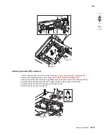
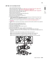
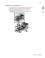
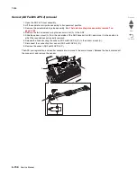
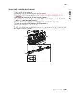
12. Disconnect the two connections from the switch (ADF left cover interlock) (D) with needle nose pliers.
13. Disconnect the connector from the document set LED (E).
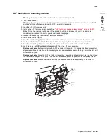
14. Disconnect the connector from the inverter solenoid assembly (F).
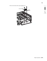
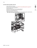
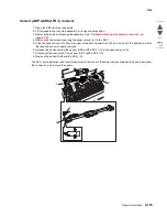
15. Release the harness from the three clamps.
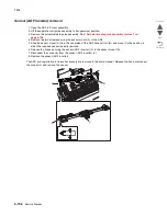
16. Remove the two front screws and the five rear screws securing the ADF media feed assembly (G) to the
ADF.
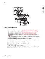
17. Release the two harness from the clamp molded into the base of the ADF.
Note:
The above clamp is located beneath the ADF registration motor. Do not excessively bend the clamp,
or it may break.
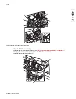
18. Remove the ADF media feed assembly (G) from the ADF.
Note:
The plunger in the inverter solenoid assembly (F) will become detached.
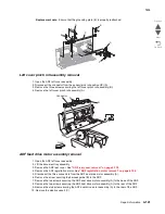
Replacement note:
Before reinstalling the ADF media feed assembly (G), ensure that the harnesses are
reinserted into their appropriate clamps.
Replacement note:
Ensure that the plunger is properly reinserted into the inverter solenoid assembly (F).
Replacement note:
Ensure that all connections are properly reconnected.
Replacement note:
When replacing the complete ADF media feed assembly, first remove the ADF left
cover assembly and the ADF registration motor from the replacement part.
P758
P786
P755
P785
P761
P754
Clamp
B
Set screw
Connectors
F
Connectors
A
Clamp
G
B
E
D
F
Clamps
Front
Rear
Summary of Contents for X945E
Page 20: ...xx Service Manual 7510 Go Back Previous Next ...
Page 25: ...Notices and safety information xxv 7510 Go Back Previous Next ...
Page 26: ...xxvi Service Manual 7510 Go Back Previous Next ...
Page 32: ...xxxii Service Manual 7510 Go Back Previous Next ...
Page 88: ...1 56 Service Manual 7510 Go Back Previous Next TTM theory ...
Page 97: ...General information 1 65 7510 Go Back Previous Next 3TM theory ...
Page 104: ...1 72 Service Manual 7510 Go Back Previous Next 1TM theory ...
Page 111: ...General information 1 79 7510 Go Back Previous Next Duplex ...
Page 432: ...3 52 Service Manual 7510 Go Back Previous Next ...
Page 475: ...Repair information 4 43 7510 Go Back Previous Next E F ...
Page 483: ...Repair information 4 51 7510 Go Back Previous Next Connectors A ...
Page 623: ...Repair information 4 191 7510 Go Back Previous Next ...
Page 653: ...Repair information 4 221 7510 Go Back Previous Next ...
Page 714: ...4 282 Service Manual 7510 Go Back Previous Next ...
Page 715: ...Connector locations 5 1 7510 Go Back Previous Next 5 Connector locations Locations ...
Page 720: ...5 6 Service Manual 7510 Go Back Previous Next Printhead Polygon mirror motor ...
Page 725: ...Connector locations 5 11 7510 Go Back Previous Next ...
Page 726: ...5 12 Service Manual 7510 Go Back Previous Next ...
Page 729: ...Connector locations 5 15 7510 Go Back Previous Next Switch media size Switch TTM media size ...
Page 765: ...Parts catalog 7 31 7510 Go Back Previous Next Assembly 29 Electrical 1 3 5 9 2 10 6 4 8 1 7 ...
Page 770: ...7 36 MFP Service Manual 7510 Go Back Previous Next Assembly 32 Electrical 4 2 1 4 3 5 7 6 8 9 ...
Page 797: ...Parts catalog 7 63 7510 Go Back Previous Next Assembly 50 1TM feed unit assembly 4 3 5 4 1 2 ...
Page 802: ...7 68 MFP Service Manual 7510 Go Back Previous Next Assembly 53 1TM drive and electrical ...
Page 804: ...7 70 MFP Service Manual 7510 Go Back Previous Next Assembly 54 3TM covers 3 5 2 4 1 ...
Page 812: ...7 78 MFP Service Manual 7510 Go Back Previous Next Assembly 58 3TM drive and electrical ...
Page 815: ...Parts catalog 7 81 7510 Go Back Previous Next Assembly 60 TTM media trays 3 5 4 3 7 2 6 8 1 ...
Page 824: ...7 90 MFP Service Manual 7510 Go Back Previous Next Assembly 67 TTM drive and electrical ...
Page 828: ...7 94 MFP Service Manual 7510 Go Back Previous Next ...
Page 836: ...I 8 Service Manual 7510 Go Back Previous Next ...
Page 844: ...I 16 Service Manual 7510 Go Back Previous Next ...


