


General information
1-35
7510
Go Back
Previous
Next
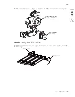
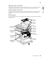
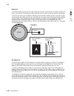
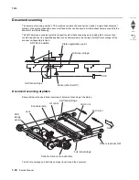
The exposure lamp is installed on the full rate carriage. As the full rate carriage travels, the document on the
platen glass is scanned and exposed with the exposure lamp.
In conjunction with the full rate carriage, the half rate carriage travels half of the stroke of the full rate carriage.
The optical image of the exposed document is reflected by the scanner 1st mirror of the full rate carriage and
directed to the scanner lens via the scanner 2nd mirror and the scanner 3rd mirror of the half rate carriage.
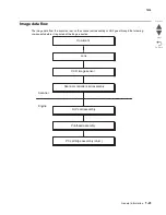
The image data is read with the scanner CCD image sensor assembly.
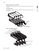
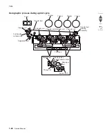
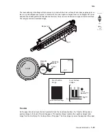
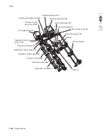
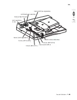
Document scanning at ADF
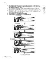
Shown below is the document feed path from the ADF.
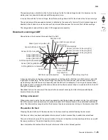
A document sheet set in the document tray assembly is fed through the ADF feed roll, ADF pick roll, and ADF
registration roll assembly. The document image is scanned at the scan position, and the document sheet is
ejected through the ADF feed-out roll assembly and the ADF exit roll assembly. For a duplex document sheet,
the image on side 1 is scanned at the scan position and then the document sheet is inverted and fed to the ADF
transport roll assembly again.
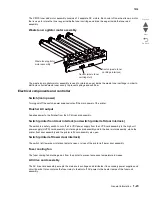
Described below is the overview of the steps before document scanning and that of simplex and duplex
document scanning modes.
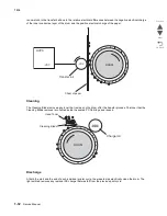
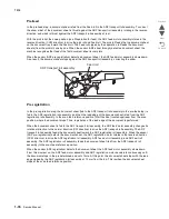
Setting a document
When a document is set on the document tray assembly and the lead edge is pushed into the tray until it stops,
the ADF document set actuator moves to place the sensor (ADF document set) in the unshielded (unblocked)
state. Then the machine recognizes that the document has been set properly, turning on the document set LED.
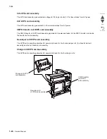
Preparation for feed
Pressing the start button with the document set in the document tray will start feeding the document.
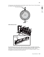
First the pick roll moves down and presses the document on the document tray to enable document feed.
The pick roll moves down with the normal rotation of the pick roll position motor assembly and it moves up with
the reverse rotation of the pick roll position motor assembly.
Upon completion of document feed, the pick roll returns to the normal (raised) position.
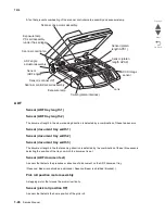
Scan position
Sensor (document tray length 2)
Sensor (inverter)
Inverter gate
Sensor (document
tray length 1)
ADF feed-out roll assembly
ADF registration roll assembly
ADF Feed roll
Sensor (ADF document set)
ADF Pick roll
ADF exit roll assembly
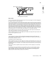
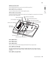
Sensor (document tray length 1)
Sensor (document tray length 2)
Sensor (document tray length 3)
Sensor (pick roll position HP)
Sensor (ADF sheet through)
Sensor (ADF pre-registration)
Sensor (ADF APS 1)
Sensor (ADF APS 2)
Sensor (ADF APS 3)
ADF transport roll assembly
Sensor (ADF registration)
Summary of Contents for X945E
Page 20: ...xx Service Manual 7510 Go Back Previous Next ...
Page 25: ...Notices and safety information xxv 7510 Go Back Previous Next ...
Page 26: ...xxvi Service Manual 7510 Go Back Previous Next ...
Page 32: ...xxxii Service Manual 7510 Go Back Previous Next ...
Page 88: ...1 56 Service Manual 7510 Go Back Previous Next TTM theory ...
Page 97: ...General information 1 65 7510 Go Back Previous Next 3TM theory ...
Page 104: ...1 72 Service Manual 7510 Go Back Previous Next 1TM theory ...
Page 111: ...General information 1 79 7510 Go Back Previous Next Duplex ...
Page 432: ...3 52 Service Manual 7510 Go Back Previous Next ...
Page 475: ...Repair information 4 43 7510 Go Back Previous Next E F ...
Page 483: ...Repair information 4 51 7510 Go Back Previous Next Connectors A ...
Page 623: ...Repair information 4 191 7510 Go Back Previous Next ...
Page 653: ...Repair information 4 221 7510 Go Back Previous Next ...
Page 714: ...4 282 Service Manual 7510 Go Back Previous Next ...
Page 715: ...Connector locations 5 1 7510 Go Back Previous Next 5 Connector locations Locations ...
Page 720: ...5 6 Service Manual 7510 Go Back Previous Next Printhead Polygon mirror motor ...
Page 725: ...Connector locations 5 11 7510 Go Back Previous Next ...
Page 726: ...5 12 Service Manual 7510 Go Back Previous Next ...
Page 729: ...Connector locations 5 15 7510 Go Back Previous Next Switch media size Switch TTM media size ...
Page 765: ...Parts catalog 7 31 7510 Go Back Previous Next Assembly 29 Electrical 1 3 5 9 2 10 6 4 8 1 7 ...
Page 770: ...7 36 MFP Service Manual 7510 Go Back Previous Next Assembly 32 Electrical 4 2 1 4 3 5 7 6 8 9 ...
Page 797: ...Parts catalog 7 63 7510 Go Back Previous Next Assembly 50 1TM feed unit assembly 4 3 5 4 1 2 ...
Page 802: ...7 68 MFP Service Manual 7510 Go Back Previous Next Assembly 53 1TM drive and electrical ...
Page 804: ...7 70 MFP Service Manual 7510 Go Back Previous Next Assembly 54 3TM covers 3 5 2 4 1 ...
Page 812: ...7 78 MFP Service Manual 7510 Go Back Previous Next Assembly 58 3TM drive and electrical ...
Page 815: ...Parts catalog 7 81 7510 Go Back Previous Next Assembly 60 TTM media trays 3 5 4 3 7 2 6 8 1 ...
Page 824: ...7 90 MFP Service Manual 7510 Go Back Previous Next Assembly 67 TTM drive and electrical ...
Page 828: ...7 94 MFP Service Manual 7510 Go Back Previous Next ...
Page 836: ...I 8 Service Manual 7510 Go Back Previous Next ...
Page 844: ...I 16 Service Manual 7510 Go Back Previous Next ...


