3-10
Service Manual
5026
Go Back
Previous
Next
Motor tests
The motor tests are run to locate noises in the printer and isolate failures between the motors, cables, and
system board.
General motor tests procedures
In some instances, when you enter a particular test, you will be given the choice to run the motor in forward or
reverse. Other times, there will only be the option to run the motor in forward direction.
In general, the test should work as follows:
1.
Select
MOTOR TESTS
from the Diagnostics Menu.
2.
Select the motor that you need to test.
3.
Check the table below for setup requirements, if any.
4.
Select the direction if a choice is offered (Forward or Reverse) or other setting for that test.
Press
or
to stop the motor and end the test.
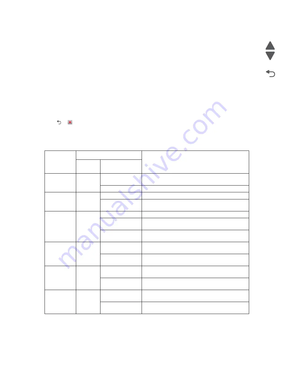
The following tests have special setup before running the test:
Motor diagnostic setup
Motor
Setup requirements
Notes
Top cover
position
Front door
position
Tray 1
N/A
Closed
• Ok
• Picks paper – use empty or remove tray
Open
Ok
Align
N/A
Closed
Ok
Open
25 V switch
• Ok
• View align mechanism
Duplex
N/A
Closed
Ok
Closed
split front door
• Ok
• View duplex mechanism (pull tray to isolate gears)
Open
25 V switch
• Ok
• Duplex mechanism disconnected from motor
Belt stepper
N/A
Closed
• No motion
• No error reported
Open
• Ok
• Belt disconnected from motor
Cartridge K – 3 N/A
Closed
• No motion
• No error reported
Open
• Ok
• Cartridge disconnected from motor
Cart MCY – 2
N/A
Closed
• No motion
• No error reported
Open
• Ok
• Cartridge disconnected from motor
Summary of Contents for CS748de
Page 13: ...Notices and safety information xiii 5026 Go Back Previous Next ...
Page 14: ...xiv Service Manual 5026 Go Back Previous Next ...
Page 20: ...xx Service Manual 5026 Go Back Previous Next ...
Page 38: ...1 18 Service Manual 5026 Go Back Previous Next ...
Page 229: ...Diagnostic aids 3 51 5026 Go Back Previous Next Theory of operation Paper path ...
Page 252: ...3 74 Service Manual 5026 Go Back Previous Next ...
Page 400: ...4 148 Service Manual 5026 Go Back Previous Next 5 Engage the gear B ...
Page 440: ...4 188 Service Manual 5026 Go Back Previous Next 9 Remove the two screws G G 18B1236 ...
Page 468: ...4 216 Service Manual 5026 Go Back Previous Next ...
Page 469: ...Connector locations 5 1 5026 Go Back Previous Next 5 Connector locations Locations ...
Page 472: ...5 4 Service Manual 5026 Go Back Previous Next ...
Page 482: ...7 8 Service Manual 5026 Go Back Previous Next Assembly 4 Right ...
Page 484: ...7 10 Service Manual 5026 Go Back Previous Next Assembly 5 Rear ...
Page 504: ...I 10 Service Manual 5026 Go Back Previous Next ...


