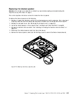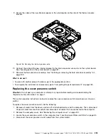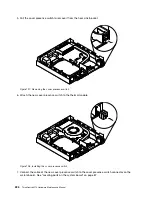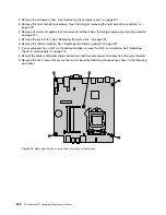
10. Carefully pivot the failing system board upward to remove it out of the chassis.
Figure 207. Removing the system board
11. Remove the microprocessor from the failing system board and install it on the new system board. See
“Replacing the microprocessor” on page 229.
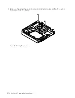
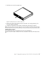
12. Install the new system board into the chassis by aligning the five screw holes in the new system board
with the corresponding mounting studs on the chassis. Then, install the five screws from screw
5
to
screw
1
in sequence to secure the system board.
Figure 208. Installing the five screws to secure the system board
13. Reinstall the thermal module. See “Replacing the thermal module” on page 227.
Chapter 11
.
Replacing FRUs (machine types: 10AX, 10AY, 10DK, 10DL, 10DM, and 10DN)
233
Summary of Contents for ThinkCentre M73 10B0
Page 6: ...iv ThinkCentre M73 Hardware Maintenance Manual ...
Page 8: ...2 ThinkCentre M73 Hardware Maintenance Manual ...
Page 15: ...Chapter 2 Safety information 9 ...
Page 19: ...Chapter 2 Safety information 13 ...
Page 20: ...1 2 14 ThinkCentre M73 Hardware Maintenance Manual ...
Page 21: ...1 2 Chapter 2 Safety information 15 ...
Page 26: ...1 2 20 ThinkCentre M73 Hardware Maintenance Manual ...
Page 27: ...1 2 Chapter 2 Safety information 21 ...
Page 30: ...24 ThinkCentre M73 Hardware Maintenance Manual ...
Page 34: ...28 ThinkCentre M73 Hardware Maintenance Manual ...
Page 62: ...56 ThinkCentre M73 Hardware Maintenance Manual ...
Page 74: ...68 ThinkCentre M73 Hardware Maintenance Manual ...
Page 92: ...86 ThinkCentre M73 Hardware Maintenance Manual ...
Page 140: ...134 ThinkCentre M73 Hardware Maintenance Manual ...
Page 244: ...238 ThinkCentre M73 Hardware Maintenance Manual ...
Page 248: ...242 ThinkCentre M73 Hardware Maintenance Manual ...
Page 254: ...248 ThinkCentre M73 Hardware Maintenance Manual ...
Page 255: ......
Page 256: ......


