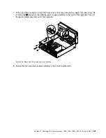
6. Remove the screw
1
and then carefully slide the solid-state drive bracket upward to remove the bracket
from the bottom of the optical drive bay.
Figure 87. Removing the solid-state drive bracket
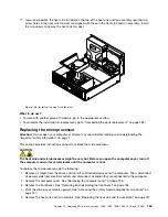
7. Remove the four screws that secure the solid-state drive to the bracket. Then, slide the drive as shown
to remove it from the bracket.
Figure 88. Removing the solid-state drive from the bracket
8. Take the new solid-state drive out of the static-protective package.
Chapter 10
.
Replacing FRUs (machine types: 10B4, 10B5, 10B6, 10B7, 10HL, and 10HM)
149
Summary of Contents for ThinkCentre M73 10B0
Page 6: ...iv ThinkCentre M73 Hardware Maintenance Manual ...
Page 8: ...2 ThinkCentre M73 Hardware Maintenance Manual ...
Page 15: ...Chapter 2 Safety information 9 ...
Page 19: ...Chapter 2 Safety information 13 ...
Page 20: ...1 2 14 ThinkCentre M73 Hardware Maintenance Manual ...
Page 21: ...1 2 Chapter 2 Safety information 15 ...
Page 26: ...1 2 20 ThinkCentre M73 Hardware Maintenance Manual ...
Page 27: ...1 2 Chapter 2 Safety information 21 ...
Page 30: ...24 ThinkCentre M73 Hardware Maintenance Manual ...
Page 34: ...28 ThinkCentre M73 Hardware Maintenance Manual ...
Page 62: ...56 ThinkCentre M73 Hardware Maintenance Manual ...
Page 74: ...68 ThinkCentre M73 Hardware Maintenance Manual ...
Page 92: ...86 ThinkCentre M73 Hardware Maintenance Manual ...
Page 140: ...134 ThinkCentre M73 Hardware Maintenance Manual ...
Page 244: ...238 ThinkCentre M73 Hardware Maintenance Manual ...
Page 248: ...242 ThinkCentre M73 Hardware Maintenance Manual ...
Page 254: ...248 ThinkCentre M73 Hardware Maintenance Manual ...
Page 255: ......
Page 256: ......

