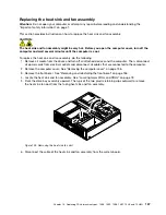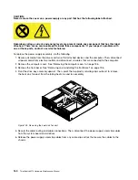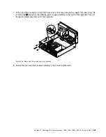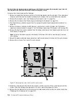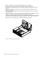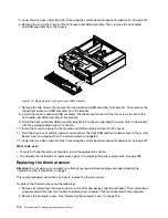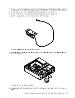
3. Remove the front bezel. See “Removing and reinstalling the front bezel” on page 136
4. Locate the thermal sensor. See “Locating major FRUs and CRUs” on page 78.
5. Pivot the drive bay assembly upward. See “Accessing the system board components and drives” on
page 137.
6. Disconnect the thermal sensor cable from the thermal sensor connector on the system board.
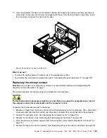
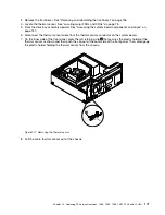
7. On the inner side of the front panel, press the left retaining clip
1
that secures the plastic holder of the
thermal sensor as shown and then push the clip out of the outer side of the front panel. Then, disengage
the plastic holder holding the thermal sensor from the chassis.
Figure 117. Removing the thermal sensor
8. Pull the entire thermal sensor out of the chassis.
Chapter 10
.
Replacing FRUs (machine types: 10B4, 10B5, 10B6, 10B7, 10HL, and 10HM)
171
Summary of Contents for ThinkCentre M73 10B0
Page 6: ...iv ThinkCentre M73 Hardware Maintenance Manual ...
Page 8: ...2 ThinkCentre M73 Hardware Maintenance Manual ...
Page 15: ...Chapter 2 Safety information 9 ...
Page 19: ...Chapter 2 Safety information 13 ...
Page 20: ...1 2 14 ThinkCentre M73 Hardware Maintenance Manual ...
Page 21: ...1 2 Chapter 2 Safety information 15 ...
Page 26: ...1 2 20 ThinkCentre M73 Hardware Maintenance Manual ...
Page 27: ...1 2 Chapter 2 Safety information 21 ...
Page 30: ...24 ThinkCentre M73 Hardware Maintenance Manual ...
Page 34: ...28 ThinkCentre M73 Hardware Maintenance Manual ...
Page 62: ...56 ThinkCentre M73 Hardware Maintenance Manual ...
Page 74: ...68 ThinkCentre M73 Hardware Maintenance Manual ...
Page 92: ...86 ThinkCentre M73 Hardware Maintenance Manual ...
Page 140: ...134 ThinkCentre M73 Hardware Maintenance Manual ...
Page 244: ...238 ThinkCentre M73 Hardware Maintenance Manual ...
Page 248: ...242 ThinkCentre M73 Hardware Maintenance Manual ...
Page 254: ...248 ThinkCentre M73 Hardware Maintenance Manual ...
Page 255: ......
Page 256: ......

