


4-10
4.5 Signals
F
UNCTIONAL
D
ESCRIPTIONS
8310/8610-8
4.5.3 ‘Zero Delta_s’
Using the
zero Delta_s signal at terminal 23 of the (1st) module P
1
, a
contouring error can be reset that has been built up in the interrupted or reset
state.
The function has been created for the case that
•
the position loop control is activated for the interrupted state (storage
location 3/47 = »active«) and
•
EMERGENCY STOP circuits are used that influence the drive system but
set the Controller only into the interrupted state.
In a triggered condition, the drive does not follow (timely-limited) the regulation
presettings of the Controller for decelerating anymore.
This results in an increased contouring distance
(Delta_s) causing a correspondingly high control
voltage.
No fault is generated in the Controller if Delta_s
stays below the S
max
maximum value (storage
location 3/42/44). When powering-up the drive
system the next time, the control voltage generated
then by the Controller may cause an inadmissible high loading of the drive.
To prevent this, the contouring distance for the corresponding axis can be set
to zero by applying High level to terminal P
1
23.
Precondition for the effectiveness of the signal:
•
parameter 3/90 of the corresponding axis is/axes are
»
active
«
•
unit of the corresponding axis (axes) is in the interrupted or reset state
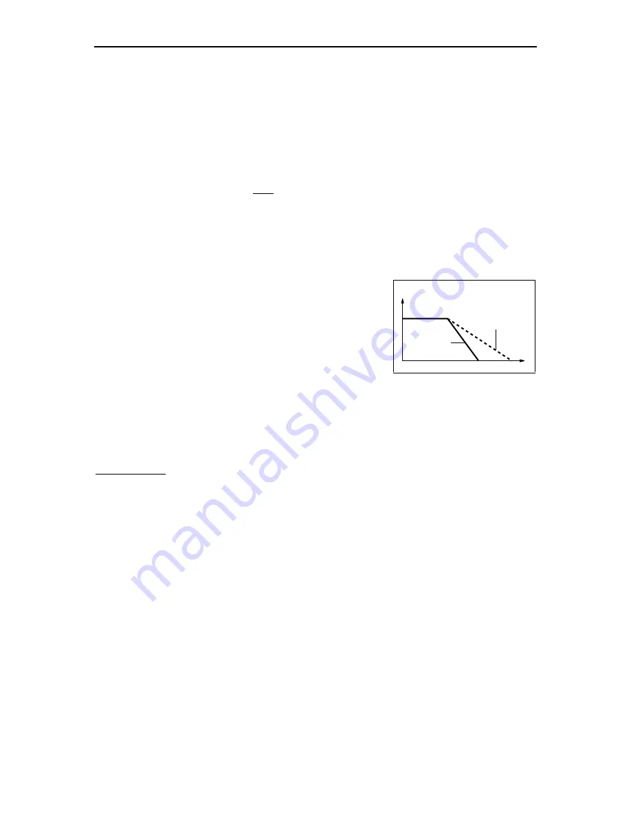
4.5.4 Drive control signals
The drive control signals include
•
release brake
•
cancel controller lock (drive enable)
The signals are output at terminal strip D. The following diagram shows the
correlation:
v
t
drive
control
E180018A
Summary of Contents for GEL 8310
Page 14: ......
Page 122: ......
Page 133: ......
Page 152: ...A 18 STORAGE LOCATIONS FOR MACHINE PARAMETERS 8310 8610 8 Remarks ...
Page 180: ......
Page 210: ......
Page 213: ...FORMS Appendix Y 8310 8610 8 i ...
Page 226: ...UPDATE INFORMATION Appendix Z 8310 8610 8 i ...