5. PICTURE DISPLAY
86
5.7.3
Selecting the Signal to Measure
To select the signal to measure, follow the procedure below.
Procedure
PIC
→
F•3 LINE SEL / NOISE
→
F•4 NOISE SETUP
→
F•2 SIGNAL: Y / G / B / R
5.7.4
Selecting the Filter
To set the cutoff frequencies of the low-pass filter and high-pass filter, follow the procedure
below.
Procedure
PIC
→
F•3 LINE SEL / NOISE
→
F•4 NOISE SETUP
→
F•3 FILTER
→
F•1 LPF: 5.5MHz / 4.4MHz / 3.6MHz / 2.7MHz / 1.4MHz / 0.7MHz / THROUGH
→
F•1 LPF: 30MHz / 24MHz / 20MHz / 15MHz / 7.5MHz / 3.7MHz / THROUGH
→
F•1 LPF: 60MHz / 48MHz / 40MHz / 30MHz / 15MHz / 7.5MHz / THROUGH
→
F•1 LPF: 120MHz / 96MHz / 80MHz / 60MHz / 30MHz / 15MHz / THROUGH
→
F•1 LPF: 240MHz / 192MHz / 160MHz / 120MHz / 60MHz / 30MHz / THROUGH
→
F•1 LPF: 0.404 / 0.323 / 0.269 / 0.202 / 0.101 / 0.0505 / THROUGH (*1)
→
F•2 HPF: OFF / ON
*1 When the input format cannot be detected, a normalized frequency is displayed.
*
The cutoff frequencies of the low-pass filter and high-pass filter vary depending on the input format.
For details, see the LV 5490 instruction manual.
5.7.5
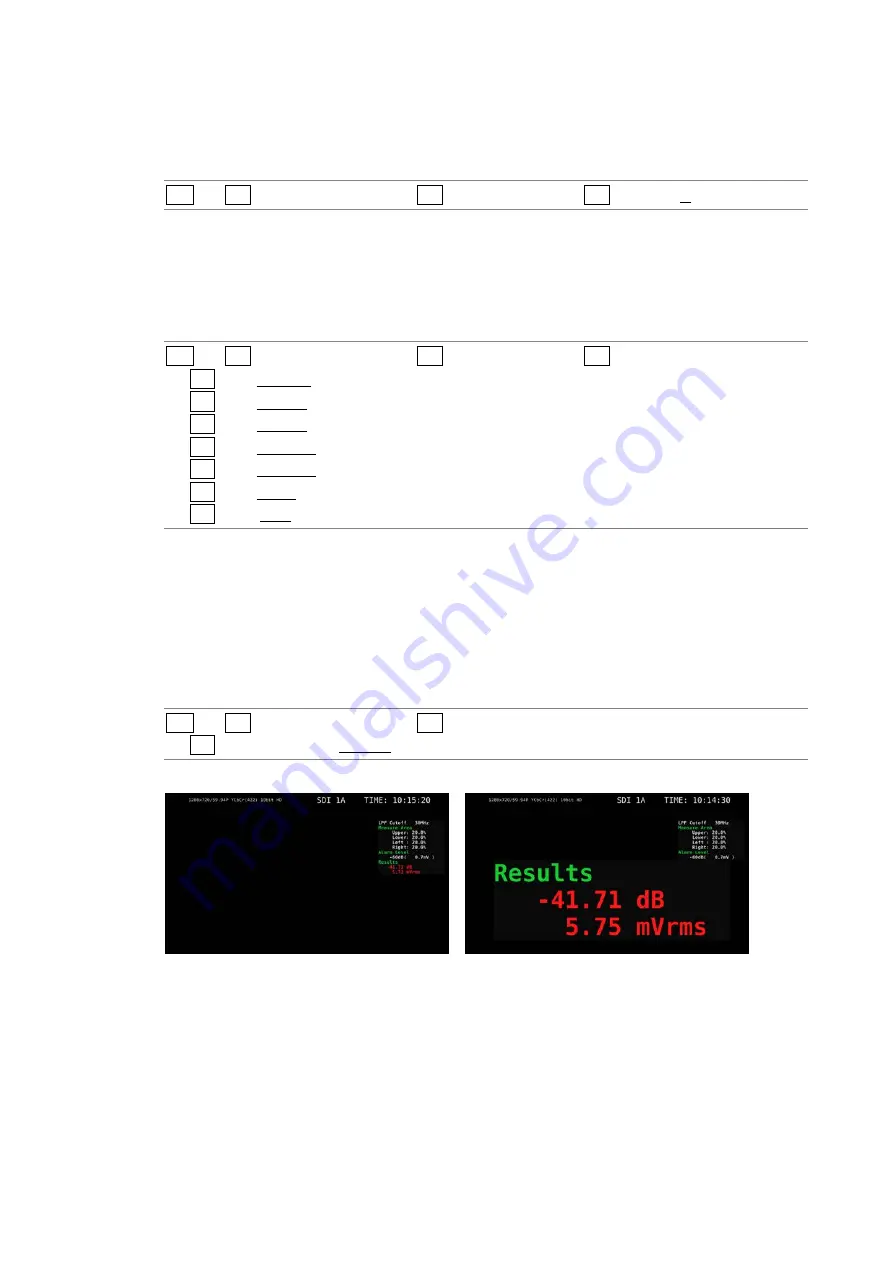
Selecting the Measurement Result Display Size
To select the measurement result display size, follow the procedure below.
Procedure
PIC
→
F•3 LINE SEL / NOISE
→
F•4 NOISE SETUP
→
F•4 RESULTS SIZE: SMALL / LARGE
RESULTS SIZE = SMALL
RESULTS SIZE = LARGE
Figure 5-30 Selecting the Measurement Result Display Size
Summary of Contents for LV 5480
Page 15: ...2 VIDEO SIGNAL WAVEFORM DISPLAY 7 SCALE UNIT HDV SDV SCALE UNIT HD SD SCALE UNIT 150 ...
Page 38: ...2 VIDEO SIGNAL WAVEFORM DISPLAY 30 COLOR MATRIX XYZ COLOR MATRIX GBR COLOR MATRIX RGB ...
Page 98: ...5 PICTURE DISPLAY 90 STATUS INFO ON Figure 5 34 Turning the information on and off ...


