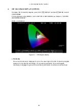
4. CIE DIAGRAM DISPLAY (SER05)
55
4.2.2
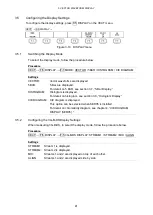
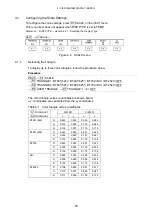
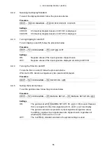
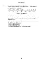
Selecting the Display Standard
To select the display standard, follow the procedure below.
Procedure
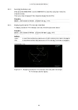
VECT
→
F•2
CIE DIAGRAM →
F•2 CIE STD: CIE1931 / CIE1976
Settings
CIE1931:
Chromaticity diagram based on CIE 1931 is displayed.
CIE1976:
Chromaticity diagram based on CIE 1976 is displayed.
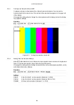
4.2.3
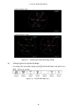
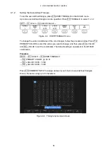
Turning Clipping On and Off
To turn clipping on and off, follow the procedure below.
Procedure
VECT
→
F•2 CIE DIAGRAM
→
F•3 CLIP: ON / OFF
Settings
ON:
Negative values of the input signal are clipped to zero.
OFF:
Negative values of the input signal are displayed according to BT.1361.
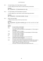
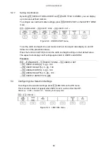
4.2.4
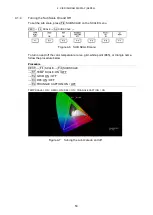
Turning the Filter On and Off
To turn the filter on and off, follow the procedure below.
When set to ON, data is averaged every two pixels and displayed.
Procedure
VECT
→
F•2 CIE DIAGRAM
→
F•4 FILTER: ON / OFF
4.2.5
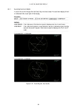
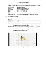
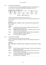
Setting the Gamma Value
To set the gamma value, follow the procedure below.
Procedure
VECT
→
F•2 CIE DIAGRAM
→
F•5 MANUAL SETUP
→
F•1 MANUAL SETUP: ON / OFF
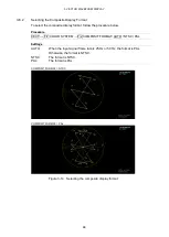
Settings
ON:
The gamma set with F•5 GAMMA SETUP(1.50 - 2.20 - 3.00) is used. However,
this is not applied to the video-signal-waveform, vector, or picture display.
The gamma calculation expression is (input signal level)^(gamma value).
In addition, negative input signal values are clipped to zero, regardless of
whether F•3 CLIP is set to on or off.
OFF:
The colorimetry standard selected in the system settings is used.
Summary of Contents for LV 5480
Page 15: ...2 VIDEO SIGNAL WAVEFORM DISPLAY 7 SCALE UNIT HDV SDV SCALE UNIT HD SD SCALE UNIT 150 ...
Page 38: ...2 VIDEO SIGNAL WAVEFORM DISPLAY 30 COLOR MATRIX XYZ COLOR MATRIX GBR COLOR MATRIX RGB ...
Page 98: ...5 PICTURE DISPLAY 90 STATUS INFO ON Figure 5 34 Turning the information on and off ...

