3. VECTOR WAVEFORM DISPLAY
40
3.4
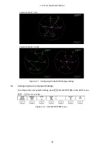
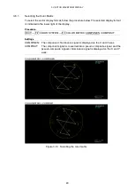
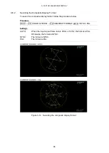
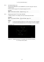
Configuring Marker Settings
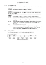
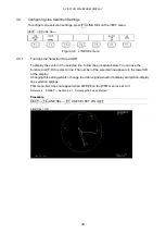
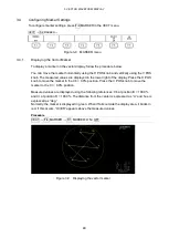
To configure marker settings, press F•4 MARKER in the VECT menu.
VECT
→
F•4
MARKER →
Figure 3-8 MARKER menu
3.4.1
Displaying the Vector Marker
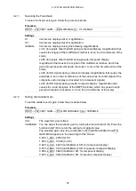
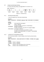
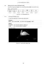
To display a marker on the vector display, follow the procedure below.
You can move the marker horizontally using the H POS knob and vertically using the V POS
knob. The measured values are displayed in the lower right of the display. Press the H POS
knob to move the marker to the Cb = 0.0% position. Press the V POS knob to move the
marker to the Cr = 0.0% position.
Measured values are displayed using the following references: Cb at position B = 100.0%
and Cr at position R = 100.0%. The distance from the center is expressed as “d,” and hue is
expressed as “deg.”
Normally, the marker is displayed in green. When if falls outside the display area, it blinks in
red. If this occurs, “OVER” appears above the measured values.
Procedure
VECT
→
F•4
MARKER →
F•1 MARKER: ON / OFF
Figure 3-9 Displaying the vector marker
Summary of Contents for LV 5480
Page 15: ...2 VIDEO SIGNAL WAVEFORM DISPLAY 7 SCALE UNIT HDV SDV SCALE UNIT HD SD SCALE UNIT 150 ...
Page 38: ...2 VIDEO SIGNAL WAVEFORM DISPLAY 30 COLOR MATRIX XYZ COLOR MATRIX GBR COLOR MATRIX RGB ...
Page 98: ...5 PICTURE DISPLAY 90 STATUS INFO ON Figure 5 34 Turning the information on and off ...

