background image

2. VIDEO SIGNAL WAVEFORM DISPLAY 

2.  VIDEO SIGNAL WAVEFORM DISPLAY 

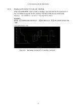
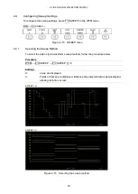
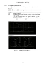
To display the video signal waveform, press WFM. 


Figure 2-1  Video signal waveform display 


●  Colorimetry 

Normally, colorimetry is not displayed, but when the colorimetry alarm is set to on in the system 
settings and a colorimetry different from the one specified is received, the alarm is indicated in 
red in the upper left of the screen. 


2.1 

Setting the Waveform Display Position 

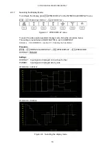
Use the V POS and H POS knobs to adjust the display position of video signal waveforms. 
On the multi display, these are valid when you press F•2 MULTI WFM on the MULTI menu. 


Figure 2-2  V POS and H POS knobs 


●  V POS Knob 

This knob adjusts the vertical position of the video signal waveform. 
Pressing the knob returns the waveform to its default position. 


●  H POS Knob 

This knob adjusts the horizontal position of the video signal waveform. 
Pressing the knob returns the waveform to its default position. 

Summary of Contents for LV 5480

Page 1: ...ST LV 5490SER05 CIE DIAGRAM LV 5490SER06 12G SDI INPUT LV 5490SER07 HDR LV 5490SER08 IP NMI LV 5490SER09 12G SDI EYE LV 5490SER10 VIDEO NOISE METER FUNCTION MENU EXPLANATIONS Thank you for purchasing Please carefully read this instruction manual and the included GENERAL SAFETY SUMMARY Please use the product safely ...

Page 2: ...e Fixed Gain 13 2 3 2 Setting the Variable Gain 13 2 3 3 Selecting the Filter 14 2 3 4 Setting the Scale Jump 16 2 4 Configuring Sweep Settings 18 2 4 1 Selecting the Sweep Method 18 2 4 2 Selecting the Line Display Format 19 2 4 3 Selecting the Field Display Format 20 2 4 4 Selecting the Horizontal Magnification 21 2 4 5 Displaying the Blanking Interval 23 2 5 Configuring Line Selection Settings ...

Page 3: ...e 3G B DS Display Settings 41 3 6 Configuring the Color System Settings 42 3 6 1 Selecting the Color Matrix 43 3 6 2 Selecting the Composite Display Format 44 3 6 3 Selecting the Setup Level 45 3 6 4 Displaying a Scale for 75 Intensity Color Bars 45 3 7 5 Bar Display 46 3 7 1 Selecting the Scale Unit 47 3 7 2 Selecting the Display Order 47 3 8 Histogram Display 48 4 CIE DIAGRAM DISPLAY SER05 49 4 ...

Page 4: ...ent Range SER03 66 5 4 Configuring CINELITE Settings 67 5 4 1 f Stop Screen Explanation 68 5 4 2 Procedure for Displaying the f Stop Screen 69 5 4 3 DISPLAY Screen Explanation 70 5 4 4 Selecting the Points to Display 73 5 4 5 Setting Measurement Points 73 5 4 6 Setting the Area of Luminance Measurement 73 5 4 7 Configuring User Defined Correction Tables 74 5 4 8 Displaying Synchronized Markers 79 ...

Page 5: ... Signals to Measure 106 7 2 Configuring the Dolby Settings option 109 7 3 Selecting the Display Mode 110 7 4 Configuring Error Detection Settings 112 7 5 Adjusting the Volume 112 7 6 Meter Display 113 7 6 1 Selecting the Scale 113 7 6 2 Selecting the Response Model 113 7 6 3 Setting the Peak Hold 114 7 6 4 Setting the Reference Level 114 7 7 Lissajous Display 115 7 7 1 Adjusting the Lissajous Curv...

Page 6: ...Moving the Display Position 156 8 5 6 Selecting the Adjustment Step Resolution 156 8 5 7 Selecting What the Function Dial Controls 157 8 5 8 Saving to USB Memory 157 8 6 Configuring Phase Difference Measurement Settings 158 8 6 1 Phase Difference Measurement Display Explanation 159 8 7 Setting the Lip Sync Measurement SER03 163 8 7 1 Selecting the Measurement Range 164 8 7 2 Updating the Measureme...

Page 7: ...e Sweep Time 193 9 7 3 Selecting the Filter 195 9 7 4 Turning Cursors On and Off 196 9 7 5 Selecting the Cursor 197 9 7 6 Moving Cursors 199 9 7 7 Selecting the X Axis Measurement Unit 199 9 7 8 Selecting the Y Axis Measurement Unit 200 9 7 9 Selecting the Display Mode 200 9 7 10 Resetting Cursors 200 9 8 Configuring the Jitter Display Settings 201 9 8 1 Selecting the Magnification 201 9 8 2 Selec...

Page 8: ...10 Installing the Plug in SER08 214 11 MENU TREE 218 11 1 WFM Menu 218 11 2 VECT Menu 220 11 3 PIC Menu 223 11 4 AUDIO Menu SER03 226 11 5 STATUS Menu 228 11 6 EYE Menu SER02 SER09 232 ...

Page 9: ...R07 HDR LV 5490SER09 12G SDI EYE Dolby option 1 2 About Trademarks and Licenses The company and product names in this document are trademarks or registered trademarks of their respective holders 1 3 About Terminology Used in this Manual SER LV 5490SER is referred to as SER Single Input Mode This refers to the mode in which on the INPUT menu F 7 DISPLAY is set to SINGLE It is a mode for measuring a...

Page 10: ...B DL 3G SDI level B dual link mapping Single link 3G B DS 3G SDI level B dual stream mapping Single link 12G 12G SDI TYPE1 Single link HD DL HD SDI dual link Dual link HD QL HD SDI quad link Quad link 3G DL 2K 3G A 3G B DL dual link Resolution 1920 2048 1080 Dual Link 3G DL 4K 3G B DS dual link Resolution 3840 4096 2160 Dual Link 3G QL 3G A 3G B DL quad link Quad link 3G Collective name for 3G lin...

Page 11: ...d with LV 5480SER20 3 Signal generation function Standard support Supported with LV 5480SER21 4 USB save destination folder name LV5490_USER LV5480_USER TELNET login and password LV5490 LV5480 FTP login and password LV5490 LV5480 SNMP MIB file name lv5490 my lv5490 my 5 1 The LV 5480SER20 must be installed to install the LV 5490SER06 or LV 5490SER08 2 The LV 5490SER06 must be installed to install ...

Page 12: ...in the upper left of the screen 2 1 Setting the Waveform Display Position Use the V POS and H POS knobs to adjust the display position of video signal waveforms On the multi display these are valid when you press F 2 MULTI WFM on the MULTI menu Figure 2 2 V POS and H POS knobs V POS Knob This knob adjusts the vertical position of the video signal waveform Pressing the knob returns the waveform to ...

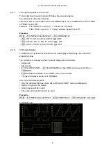
Page 13: ...PLAY F 1 WFM INTEN 128 0 127 2 2 2 Selecting the Vector Color To select the video signal waveform color follow the procedure below On the multi display the following colors are assigned to the video signal waveforms Y white Cb cyan Cr magenta G green B blue R red X white Y white Z white COMPOSIT white Procedure when not measuring 3G B DS WFM F 1 INTEN SCALE DISPLAY F 2 WFM COLOR WHITE YELLOW CYAN ...

Page 14: ...YZ the scale unit is set to HD SD or 150 When COLOR MATRIX is set to COMPOSIT and the composite display format is NTSC this is fixed to HD SD When the composite display format is PAL this is fixed to HDV SDV Video signal white 100 becomes 0 7 V or 100 on the scale Video signal black 0 becomes 0 V or 0 on the scale Reference COLOR MATRIX section 2 7 1 Selecting the Color Matrix Procedure WFM F 1 IN...

Page 15: ...2 VIDEO SIGNAL WAVEFORM DISPLAY 7 SCALE UNIT HDV SDV SCALE UNIT HD SD SCALE UNIT 150 ...

Page 16: ...2 VIDEO SIGNAL WAVEFORM DISPLAY 8 SCALE UNIT 1023 SCALE UNIT 1023 255 SCALE UNIT 3FF Figure 2 5 Selecting the scale unit ...

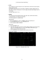
Page 17: ...ale that matches the peak levels of the color difference signals for 75 intensity color bars follow the procedure below Reference COLOR MATRIX section 2 7 1 Selecting the Color Matrix Procedure WFM F 1 INTEN SCALE DISPLAY F 3 WFM SCALE F 4 75 COLOR SCALE ON OFF 75 COLOR SCALE ON Figure 2 6 Displaying a scale for 75 intensity color bars ...

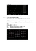
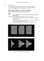
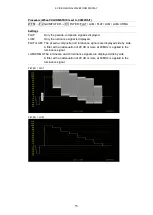
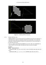
Page 18: ...ignal waveform display mode follow the procedure below This setting is invalid when COLOR MATRIX is set to COMPOSIT Reference COLOR MATRIX section 2 7 1 Selecting the Color Matrix Procedure WFM F 1 INTEN SCALE DISPLAY F 4 WFM DISPLAY F 1 WFM MODE OVERLAY PARADE Settings OVERLAY Input signal is displayed on top of each other PARADE Input signal is displayed side by side WFM MODE OVERLAY WFM MODE PA...

Page 19: ...OFF F 4 CH3 Cr CH3 Z CH3 R CH3 B ON OFF 2 2 9 4Y Parade Display To extract the Y signals from channels A to D and display them side by side follow the procedure below The conditions for displaying the 4Y parade display are listed below Single link Simul mode F 7 COLOR SYSTEM F 1 COLOR MATRIX on the WFM menu is set to YCbCr or COMPOSIT F 6 OPERATE CH MODE on the INPUT menu is set to COM The layout ...

Page 20: ...S to select the display mode follow the procedure below Procedure WFM F 1 INTEN SCALE DISPLAY F 4 WFM DISPLAY F 5 3G B DS DISPLAY STREAM1 STREAM2 MIX ALIGN Settings STREAM1 Stream 1 is displayed STREAM2 Stream 2 is displayed MIX Streams 1 and 2 are displayed on top of each other ALIGN Streams 1 and 2 are displayed side by side 3G B DS DISPLAY MIX ...

Page 21: ...elow Procedure WFM F 2 GAIN FILTER F 2 GAIN MAG X1 X5 2 3 2 Setting the Variable Gain To set the variable video signal waveform gain follow the procedure below Procedure WFM F 2 GAIN FILTER F 1 GAIN VARIABLE CAL VARIABLE Settings CAL The waveform gain is fixed VARIABLE You can adjust the waveform gain by turning the function dial F D Press the function dial F D to return the setting to its default...

Page 22: ... 2 GAIN FILTER F 3 FILTER FLAT LOWPASS Settings FLAT A filter with a flat frequency response over the entire bandwidth of the input signal is applied LOWPASS A low pass filter with the following characteristics is applied At 40 MHz 20 dB attenuation or more when the input signal is 1080 60P 59 94P or 50P At 20 MHz 20 dB attenuation or more when the input signal is 3G HD or HD DL excluding 1080 60P...

Page 23: ... LUM Only the luminance signal is displayed FLAT LUM The pseudo composite and luminance signals are displayed side by side A filter with an attenuation of 20 dB or more at 40 MHz is applied to the luminance signal LUM CRMA The luminance and chrominance signals are displayed side by side A filter with an attenuation of 20 dB or more at 40 MHz is applied to the luminance signal FILTER FLAT FILTER LU...

Page 24: ...rocedure below You can view the area that is currently displayed with respect to the entire waveform on the scale shown on the right side of the screen This menu appears when F 1 GAIN VARIABLE is set to CAL When set to VARIABLE the value is fixed to 0 and the scale on the right side of the screen does not appear Procedure WFM F 2 GAIN FILTER F 4 SCALE JUMP 0 10 20 30 40 50 60 70 80 90 CURSOR when ...

Page 25: ...e Y axis cursor and the area near the currently selected cursor mark is expanded An example operation is indicated below Preparation 1 On the CURSOR menu set F 1 CURSOR to ON and F 2 XY SEL to Y 2 On the GAIN FILTER menu set F 2 GAIN MAG to X5 3 Set F 4 SCALE JUMP to CURSOR Operation 4 Set F 2 GAIN MAG to X1 5 Move the Y axis cursor to the area you want to display expanded You can move the cursor ...

Page 26: ...e 2 15 SWEEP menu 2 4 1 Selecting the Sweep Method To select the video signal waveform sweep method follow the procedure below Procedure WFM F 3 SWEEP F 1 SWEEP H V Settings H Lines are displayed V Fields or frames are displayed Because the sampled data is downsampled aliasing distortion occurs SWEEP H SWEEP V Figure 2 16 Selecting the sweep method ...

Page 27: ...re WFM F 3 SWEEP F 2 H SWEEP 1H 2H Settings 1H One line is displayed 2H Two lines are displayed This cannot be selected in the following situations When using 4K When F 1 INTEN SCALE DISPLAY F 4 WFM DISPLAY F 1 WFM MODE is set to PARADE When F 7 COLOR SYSTEM F 1 COLOR MATRIX is set to COMPOSIT H SWEEP 1H H SWEEP 2H Figure 2 17 Selecting the line display format ...

Page 28: ...ttings 1V One field is displayed 2V One frame is displayed This option cannot be selected when the input signal is progressive V SWEEP 1V V SWEEP 2V Figure 2 18 Selecting the field display format Furthermore when the input signal is interlace or segmented frame and F 2 V SWEEP is set to 1V to select which field is displayed follow the procedure below Procedure WFM F 3 SWEEP F 4 FIELD FIELD1 FIELD2...

Page 29: ...s No No Yes Settable No Not settable Procedure WFM F 3 SWEEP F 3 SWEEP MAG X1 X10 X20 X40 ACTIVE BLANK Settings X1 The video signal waveforms are displayed so that they fit on the screen X10 The video signal waveforms are magnified from the center of the display to 10 times the size of X1 X20 The video signal waveforms are magnified from the center of the display to 20 times the size of X1 X40 The...

Page 30: ...2 VIDEO SIGNAL WAVEFORM DISPLAY 22 SWEEP MAG X10 SWEEP MAG ACTIVE SWEEP MAG BLANK Figure 2 19 Horizontal magnifications ...

Page 31: ...g the Color Matrix Procedure WFM F 3 SWEEP F 5 BLANKING REMOVE V VIEW H VIEW ALL VIEW Settings REMOVE Only the active interval is displayed V VIEW The active interval and the vertical blanking interval are displayed H VIEW The active interval and the horizontal blanking interval are displayed This option cannot be selected when COLOR MATRIX is set to COMPOSIT ALL VIEW The entire input signal is di...

Page 32: ...he procedure below You can use the function dial F D to select a line The number of the selected line appears in the lower left of the display Changing this setting will also change the vector display and picture display line selection settings This menu item does not appear when SWEEP is set to V Reference SWEEP Section 2 4 1 Selecting the Sweep Method Procedure WFM F 4 LINE SEL F 1 LINE SELECT O...

Page 33: ...ield 2 can be selected Example 564 to 1125 FRAME All lines can be selected Example 1 to 1125 2 6 Configuring Cursor Settings To configure cursor settings press F 5 CURSOR on the WFM menu WFM F 5 CURSOR Figure 2 23 CURSOR menu 2 6 1 Turning Cursors On and Off To turn cursors on and off follow the procedure shown below The REF cursor is displayed in blue and the DELTA cursor is displayed in green Th...

Page 34: ... SEL Y Figure 2 24 Selecting the cursor 2 6 3 Moving Cursors To move a cursor follow the procedure shown below to select a cursor Then move the cursor by turning the function dial F D Triangles appear on both ends of the selected cursor You can also select a cursor by pressing the function dial F D Each time you press the function dial F D the selected cursor switches from REF to DELTA to TRACK an...

Page 35: ...ressed as 64 to 940 This option cannot be selected when COLOR MATRIX is set to COMPOSIT CBCR signal measurement is not supported HEX Values are displayed in hexadecimal with 0 to 100 expressed as 040 to 3AC This option cannot be selected when COLOR MATRIX is set to COMPOSIT CBCR signal measurement is not supported HDR Values are displayed as a percentage or cd m2 You can select this option when SE...

Page 36: ...e shown below except when F 3 Y UNIT is set to R The display unit is the unit specified with F 3 Y UNIT or F 3 X UNIT If F 1 CURSOR is set to ON XY the value is displayed on the cursor selected with F 2 XY SEL Procedure WFM F 5 CURSOR F 5 CURSOR VALUE ON OFF CURSOR VALUE ON Figure 2 25 Turning the cursor value display on and off ...

Page 37: ...YSTEM F 1 COLOR MATRIX YCbCr XYZ GBR RGB COMPOSIT Settings YCbCr The YCBCR signal is displayed without changes This option cannot be selected when the input signal is RGB or XYZ XYZ The XYZ signal is displayed without changes This option cannot be selected when the input signal is YCBCR or RGB GBR The input signal is converted into a GBR signal and displayed RGB The input signal is converted into ...

Page 38: ...2 VIDEO SIGNAL WAVEFORM DISPLAY 30 COLOR MATRIX XYZ COLOR MATRIX GBR COLOR MATRIX RGB ...

Page 39: ...r matrix 2 7 2 Turning the Luminance Signal On and Off When F 1 COLOR MATRIX is set to GBR or RGB to turn the luminance signal Y on and off follow the procedure below Procedure WFM F 7 COLOR SYSTEM F 2 YGBR ON OFF F 2 YRGB ON OFF YGBR ON Figure 2 28 Turning the luminance signal on and off ...

Page 40: ...te is 25 Hz or 50 Hz the format is PAL Otherwise the format is NTSC NTSC The format is NTSC The scale is fixed to percentage PAL The format is PAL The scale is fixed to V 2 7 4 Selecting the Setup Level When F 1 COLOR MATRIX is set to COMPOSIT to select the setup level follow the procedure below This menu does not appear if the composite display format is PAL Procedure WFM F 7 COLOR SYSTEM F 5 SET...

Page 41: ... vector display scale has the following qualities Frame 5 of the full scale value of 0 7 V for component display 3 of the full scale value of 0 7 V for pseudo composite display Circle 20 with respect to green Blanking interval Normally blanking interval is not displayed with vector waveforms but if SWEEP MAG is set to BLANK on the WFM menu or BLANKING is set to REMOVE it is displayed Colorimetry T...

Page 42: ...waveform color follow the procedure below Procedure when not measuring 3G B DS VECT F 1 INTEN SCALE F 2 VECT COLOR WHITE YELLOW CYAN GREEN MAGENTA RED BLUE Procedure when measuring 3G B DS VECT F 1 INTEN SCALE F 2 VECT COLOR F 1 STREAM1 COLOR WHITE YELLOW CYAN GREEN MAGENTA RED BLUE F 2 STREAM2 COLOR WHITE YELLOW CYAN GREEN MAGENTA RED BLUE 3 1 3 Adjusting the Scale Intensity To configure the scal...

Page 43: ...urn the display of the I and Q axes on and off follow the procedure below This menu item does not appear when VECT SCALE is set to DCI or BT 2020 When the full scale value of 0 7 V is 100 the I and Q axes are displayed at the following values Table 3 1 Displaying the I and Q axes I Axis Q Axis G 44 559 37 056 B 27 865 84 085 R 69 120 62 417 Procedure VECT F 1 INTEN SCALE F 3 IQ AXIS ON OFF IQ AXIS...

Page 44: ... is SD and a 100 color bar signal is being applied the peak levels match the ends of the scale BT 709 A scale defined in ITU R BT 709 is displayed When the input signal is HD and a 100 color bar signal is being applied the peak levels match the ends of the scale DCI A scale defined in DCI is displayed BT 2020 A scale defined in ITU R BT 2020 is displayed When the input signal is 4K the division tr...

Page 45: ...cale when the burst signal of the composite vector display is converted into component signals x2 63 for SD signals during pseudo composite display magnification that causes the I and Q signals of the SMPTE colorbar which has gone through pseudo composite conversion to lie on the circumference of the scale 3 2 2 Setting the Variable Gain To set the variable vector gain follow the procedure below P...

Page 46: ... line follow the procedure below You can use the function dial F D to select a line The number of the selected line appears in the lower left of the display Changing this setting will also change the video signal waveform display and picture display line selection settings This menu item does not appear when SWEEP on the WFM menu is set to V Reference SWEEP Section 2 4 1 Selecting the Sweep Method...

Page 47: ...to set the line selection range follow the procedure below Changing this setting will also change the selected line on the video signal waveform picture and status data dump displays Procedure VECT F 3 LINE SEL F 2 FIELD FIELD1 FIELD2 FRAME Settings FIELD1 A line from field 1 can be selected Example 1 to 563 FIELD2 A line from field 2 can be selected Example 564 to 1125 FRAME All lines can be sele...

Page 48: ...splayed in the lower right of the display Press the H POS knob to move the marker to the Cb 0 0 position Press the V POS knob to move the marker to the Cr 0 0 position Measured values are displayed using the following references Cb at position B 100 0 and Cr at position R 100 0 The distance from the center is expressed as d and hue is expressed as deg Normally the marker is displayed in green When...

Page 49: ... 7 5 Bar Display HISTOGRAM Histogram is displayed For detail on histogram see section 3 8 Histogram Display CIE DIAGRAM CIE diagram is displayed This option can be selected when SER05 is installed For detail on chromaticity diagram see chapter 4 CIE DIAGRAM DISPLAY SER05 3 5 2 Configuring the 3G B DS Display Settings When measuring 3G B DS to select the display mode follow the procedure below Proc...

Page 50: ...X 3G B DS DISPLAY ALIGN Figure 3 11 Configuring the 3G B DS display settings 3 6 Configuring the Color System Settings To configure the color system settings press F 7 COLOR SYSTEM on the VECT menu VECT F 7 COLOR SYSTEM Figure 3 12 COLOR SYSTEM menu ...

Page 51: ...lay Procedure VECT F 7 COLOR SYSTEM F 1 COLOR MATRIX COMPONEN COMPOSIT Settings COMPONEN The component chrominance signal is displayed on the X and Y axes COMPOSIT The component signal is converted into a pseudo composite signal and the pseudo composite signal s chrominance signal is displayed on the X and Y axes COLOR MATRIX COMPONEN COLOR MATRIX COMPOSIT Figure 3 13 Selecting the color matrix ...

Page 52: ...cedure below Procedure VECT F 7 COLOR SYSTEM F 2 COMPOSIT FORMAT AUTO NTSC PAL Settings AUTO When the input signal frame rate is 25 Hz or 50 Hz the format is PAL Otherwise the format is NTSC NTSC The format is NTSC PAL The format is PAL COMPOSIT FORMAT NTSC COMPOSIT FORMAT PAL Figure 3 14 Selecting the composite display format ...

Page 53: ...3 6 4 Displaying a Scale for 75 Intensity Color Bars To display a scale for 75 intensity color bars follow the procedure below Procedure VECT F 7 COLOR SYSTEM F 4 COLOR BAR 100 75 Settings 100 A scale that matches the peak levels of 100 intensity color bars is displayed 75 A scale that matches the peak levels of 75 intensity color bars is displayed COLOR BAR 75 Figure 3 15 Displaying a scale for 7...

Page 54: ...Lower on the status menu are displayed in red Reference Luminance Upper Lower Section 8 2 4 Error Setup 4 GBR Levels that fall outside of the range that you set using Gamut Upper and Gamut Lower on the status menu are displayed in red Reference Gamut Upper Lower Section 8 2 3 Error Setup 3 CMP Levels that fall outside of the range that you set using Composite Upper and Composite Lower on the statu...

Page 55: ...splay unit is mV Depending on the composite display format the scale differs as follows NTSC 100 700 mV YGBR 100IRE 714 mV CMP PAL 100 IRE 700 mV 5BAR SCALE 5BAR SCALE mV Figure 3 18 Selecting the scale unit 3 7 2 Selecting the Display Order To select the 5 bar display order follow the procedure shown below Procedure VECT F 2 5BAR SEQUENCE GBR RGB Settings GBR From the left the signals are display...

Page 56: ...lect HISTOGRAM The histogram display shows the image data distribution by plotting the luminance level on the horizontal axis and the number of pixels at each luminance level on the vertical axis If SER07 is installed you can change the horizontal scale See section 6 2 1 Histogram Display Figure 3 20 Histogram display ...

Page 57: ...et to VECTOR or HISTOGRAM see chapter 3 VECTOR WAVEFORM DISPLAY MODE CIE DIAGRAM Figure 4 1 CIE diagram display Colorimetry The current colorimetry is displayed in cyan in the lower right of the CIE chromaticity diagram However for 3G DL 4K and 3G QL if you select a payload ID the current applied colorimetry is displayed in yellow if the colorimetry information of all links are not matched ...

Page 58: ... 625 BT 709 DCI BT 2020 OFF F 5 USER TRIANGLE F 1 TRIANGLE 1 2 OFF The color triangle vertex coordinates are shown below u v coordinates are calculated from the xy coordinates Table 4 1 Color triangle vertex coordinates F 1 TRIANGLE1 F 2 TRIANGLE2 CIE1931 CIE1976 x y u v BT 601 525 R 0 630 0 340 0 433 0 526 G 0 310 0 595 0 130 0 563 B 0 155 0 070 0 176 0 178 BT 601 625 R 0 640 0 330 0 451 0 523 G ...

Page 59: ...inates of the color triangle follow the procedure below Press F 2 PRIMARY COLOR to select the vertex you want to change and then press F 3 x VALUE and F 4 y VALUE to set the coordinates The default setting is equivalent to the BT 2020 coordinates Procedure VECT F 1 SCALE F 5 USER TRIANGLE F 2 PRIMARY COLOR G B R F 3 x VALUE 0 000 1 000 F 4 y VALUE 0 000 1 000 Press F 5 COMMENT INPUT to assign name...

Page 60: ...character 4 1 3 Selecting the Color Scale To select the horseshoe shaped color scale follow the procedure below Procedure VECT F 1 SCALE F 3 COLOR B G COLOR B G WHITE B G BLACK Settings B G COLOR The color scale is displayed The background is black and the waveform is displayed according to the luminance level B G WHITE The color scale is not displayed The background is white and the waveform is d...

Page 61: ...CALE Figure 4 6 SUB SCALE menu To turn on and off the color temperature curve grid white point D65 or triangle name follow the procedure below Procedure VECT F 1 SCALE F 4 SUB SCALE F 1 TEMP SCALE ON OFF F 2 GRID ON OFF F 3 D65 ON OFF F 4 TRIANGLE CAPTION ON OFF TEMP SCALE ON GRID ON D65 ON TRIANGLE CAPTION ON Figure 4 7 Turning the sub scale on and off ...

Page 62: ...menu VECT F 2 CIE DIAGRAM Figure 4 8 CIE DIAGRAM menu 4 2 1 Selecting the Display Type To select the display type follow the procedure below Procedure VECT F 2 CIE DIAGRAM F 1 DISP TYPE DIAGRAM TEMP Settings DIAGRAM The chromaticity diagram is displayed TEMP The color temperature is displayed DISP TYPE TEMP Figure 4 9 Selecting the display type ...

Page 63: ...cording to BT 1361 4 2 4 Turning the Filter On and Off To turn the filter on and off follow the procedure below When set to ON data is averaged every two pixels and displayed Procedure VECT F 2 CIE DIAGRAM F 4 FILTER ON OFF 4 2 5 Setting the Gamma Value To set the gamma value follow the procedure below Procedure VECT F 2 CIE DIAGRAM F 5 MANUAL SETUP F 1 MANUAL SETUP ON OFF Settings ON The gamma se...

Page 64: ...diagram follow the procedure shown below You can move the cursor horizontally using the H POS knob and vertically using the V POS knob The measured values are shown in the upper right of the display Press the H POS and V POS knobs to move the cursor to the following position Chromaticity diagram display x y u v 0 0 Color temperature display Lower left of the display Procedure VECT F 4 CURSOR F 1 C...

Page 65: ...tween the Color and Monochrome Displays To switch between the color and monochrome displays follow the procedure below Procedure PIC F 1 ADJUST F 1 MONO COLOR COLOR MONO 5 1 2 Setting the Chroma Gain To switch the chroma gain follow the procedure below Procedure PIC F 1 ADJUST F 2 CHROMA UP NORMAL UP Settings NORMAL The chroma gain is set to the value that you have set using F 5 GAIN BIAS F 1 GAIN...

Page 66: ...e PIC F 1 ADJUST F 4 CONTRAST 0 0 100 0 200 0 5 1 5 Adjusting the Gain To adjust the gain press F 1 GAIN on the GAIN BIAS menu PIC F 1 ADJUST F 5 GAIN BIAS F 1 GAIN Figure 5 3 GAIN menu To adjust the gain separately for the R G B and chroma signals follow the procedure below Press the function dial F D to return the setting to its default value 100 0 When F 2 CHROMA UP is set to UP F 4 CHROMA GAIN...

Page 67: ... to return the setting to its default value 0 0 Procedure PIC F 1 ADJUST F 5 GAIN BIAS F 2 BIAS F 1 R BIAS 50 0 0 0 50 0 F 2 G BIAS 50 0 0 0 50 0 F 3 B BIAS 50 0 0 0 50 0 5 2 Configuring Marker Settings To configure marker settings press F 2 MARKER in the PIC menu This menu item does not appear when SIZE is set to a value other than FIT Reference SIZE Section 5 8 1 Selecting the Display Size PIC F...

Page 68: ... not displayed 17 9 A 17 9 aspect marker is displayed This option cannot be selected when the input signal is a 17 9 frame signal or an SD signal 16 9 A 16 9 aspect marker is displayed This option cannot be selected when the input signal is a 16 9 frame signal 14 9 A 14 9 aspect marker is displayed 13 9 A 13 9 aspect marker is displayed 4 3 A 4 3 aspect marker is displayed This option cannot be se...

Page 69: ...erved 1101 4 3Full14 9 0 4 3 1101 Full frame 4 3 image with alternative 14 9 center 1110 16 9LB14 9 0 4 3 1110 Letterbox 16 9 image with alternative 14 9 center 1111 16 9LB4 3 0 4 3 1111 Letterbox 16 9 image with alternative 4 3 center 0000w UNDEFINED 1 16 9 0000 Undefined 0001w RESERVED 1 16 9 0001 Reserved 0010w Full Frame 1 16 9 0010 Full frame 16 9 image the same as the coded frame 0011w 14 9P...

Page 70: ...e aspect marker shadow follow the procedure below The larger the number the darker the shadow If you specify 0 the aspect marker will be indicated with a line Press the function dial F D to return the setting to its default value 50 Procedure PIC F 2 MARKER F 4 ASPECT SHADOW 0 50 100 ASPECT SHADOW 50 Figure 5 7 Setting the aspect shadow ...

Page 71: ...splayed This option cannot be selected when the input signal is 4K USER1 A marker that has been set with F 1 USER1 WIDTH and F 2 USER1 HEIGHT for F 3 USER1 2 SET is displayed OFF A safe action marker is not displayed 5 2 6 Setting the Safe Title Marker To display the safe title marker follow the procedure below When an aspect marker is displayed the safe action marker is displayed relative to the ...

Page 72: ...s below Press the function dial F D to return the width and height settings to their default value The aspect ratio display on off setting applies both to USER1 and USER2 Procedure PIC F 2 MARKER F 5 SAFETY ZONE F 3 USER1 2 SET F 1 USER1 WIDTH 0 90 100 F 2 USER1 HEIGHT 0 90 100 F 3 USER2 WIDTH 0 80 100 F 4 USER2 HEIGHT 0 80 100 F 5 USER1 2 ASPECT ON OFF 5 3 Configuring Line Selection Settings To c...

Page 73: ...FF LINE SELECT ON Figure 5 11 Turning line selection on and off 5 3 2 Setting the Line Selection Range When F 1 LINE SELECT is set to ON and the input signal format is interlaced or segmented frame to set the line selection range follow the procedure below Changing this setting will also change the selected line on the video signal waveform vector and status data dump displays Procedure PIC F 3 LI...

Page 74: ...rement range follow the procedure below Markers are displayed at the specified lines You can also set these using AV PHASE SETUP of the STATUS menu but here you can set them while viewing the picture For details on the settings section 8 7 3 Setting the Measurement Range Procedure PIC F 3 LINE SEL F 3 AV PHASE F 1 AV MEASURE TOP 0 50 100 F 2 AV MEASURE LEFT 0 99 F 3 AV MEASURE RIGHT 0 99 F 4AV MEA...

Page 75: ...itch to the CINELITE display follow the procedure below Procedure PIC F 4 CINELITE F 1 CINELITE DISPLAY OFF f Stop DISPLAY CINEZONE Settings OFF A cinelite is not displayed f Stop The f Stop screen is displayed This option cannot be selected in simul mode or 3G B DS DISPLAY The DISPLAY screen is displayed This option cannot be selected in simul mode or 3G B DS CINEZONE The CINEZONE screen is displ...

Page 76: ...F 4 CINELITE F 1 CINELITE DISPLAY F 2 f Stop SETUP Figure 5 14 f Stop screen 1 Reference Position The position where the cursors intersected when F 4 18 REF SET was pressed is displayed in red This is the reference position for f stop measurement 2 Cursor You can set up to three measurement points The cursor coordinates are indicated using sample numbers and line numbers Additionally The f Stop va...

Page 77: ...lso use a user defined gamma correction table that matches the gamma characteristics of the camera that you are using For details see section 5 4 7 Configuring User Defined Correction Tables The selected gamma correction value is indicated in the upper left of the display 6 Press F 7 up menu 7 Make sure that the cursors are over the 18 gray chart and press F 4 18 REF SET The f Stop value for 18 gr...

Page 78: ...DE VALUE DEC levels Use F 4 UNIT SELECT to select the display format The measured values are typically displayed using white but they are displayed using yellow when the luminance level is 80 or more or 0 or less Y Display Luminance levels are indicated as percentages Figure 5 15 Y display RGB Display Each R G and B level is indicated using a percentage The levels are also indicated using bars on ...

Page 79: ...e value of an RGB level that is 0 or less is 0 Figure 5 17 RGB255 display CODE VALUE Display The SDI signal video data is displayed in hexadecimal notation If the input signal is YCbCr the data is displayed in YCbCr If the input signal is RGB the data is displayed in RGB If the input signal is XYZ data is displayed using values converted into RGB with black level offset added You can select CODE V...

Page 80: ...he input signal is YCbCr the data is displayed in YCbCr If the input signal is RGB the data is displayed in RGB If the input signal is XYZ data is displayed using values converted into RGB with black level offset added You can select CODE VALUE DEC when F 3 MEAS SIZE is 1 1 Figure 5 19 CODE VALUE DEC display ...

Page 81: ... the blanking interval To display cursors that do not appear move them within the screen The measurement point settings made on the menus accessed by pressing fStop and DISPLAY are the same Procedure PIC F 4 CINELITE F 2 f Stop SETUP F 1 MEAS POS P1 P2 P3 F 2 DISPLAY SETUP F 1 MEAS POS P1 P2 P3 5 4 6 Setting the Area of Luminance Measurement To select the area of luminance measurement follow the p...

Page 82: ...0 Creating User Defined Correction Tables Using the LV 5490 You can create and store up to three user defined correction tables on the LV 5490 As an example the following procedure shows how to create a user defined correction table that matches a camera s gamma characteristics Set the camera s f Stop value to F5 6 beforehand and put an 18 gray chart in the area that you will film 1 Adjust the lig...

Page 83: ...rst when you create a new user defined correction table 8 Press F 1 CLEAR YES To cancel the initialization of a user defined correction table press F 3 CLEAR NO 9 Place the cursors over the 18 gray chart 10 Press F 4 CAL F and select 5 6 11 Press F 3 CAL SET The luminance level when the camera f Stop value is F5 6 is input into Lev in the user defined correction table To delete a line of data pres...

Page 84: ...rs is 416 10 bit value the f Stop value at that point 3 0 is displayed as the REF value Figure 5 21 User defined correction tables When the above user defined correction tables are used f Stop values are indicated as shown below The values between specified values are interpolated linearly When Lv 152 f Stop 3 0 When Lv 240 f Stop 2 0 When Lv 328 f Stop 1 0 When Lv 416 f Stop 0 0 When Lv 504 f Sto...

Page 85: ...ment Comment Comment Data Data Data Data Data Data Comment When you create a correction table make sure that it conforms to the specifications listed below Overall File Specifications File Type ASCII text file Extension CLT End of Line Character CR LF Number of Lines 5000 or less Number of Characters per Line 255 or less including CR LF File Name Length 20 characters or less excluding the extensio...

Page 86: ...vel of 100 is defined as 940 10 bits 4 3760 12 bits A luminance level of 0 is defined as 64 10 bits 4 256 12 bits Separator Enter a single tab code Output Value Enter a value from 0 to 65535 16 bits 2 Save the user defined correction table to USB memory and connect the USB memory to the LV 5490 Save the correction table in the following directory USB memory LV5490_USER CLT TEST CLT for example 3 P...

Page 87: ...yed using the name determined by its NAME keyword 5 4 8 Displaying Synchronized Markers To synchronize the markers on the vector display and video signal waveform display to measurement points P1 to P3 and REF that you specify on the CINELITE display follow the procedure below Synchronized markers can be displayed only when an f Stop screen or DISPLAY screen is shown in the same multi screen displ...

Page 88: ...rrespond to what luminance levels by looking at the scale on the right of the display If F 2 UPPER is 1 greater than F 3 LOWER and you lower the value of F 2 UPPER the value of F 3 LOWER is automatically lowered to maintain a difference of 1 between the two values In the same way if you raise the value of F 3 LOWER the value of F 2 UPPER is automatically raised to maintain a difference of 1 betwee...

Page 89: ...s displayed such that luminance levels at and above F 2 UPPER are displayed using red and levels below F 3 LOWER are displayed using blue To set the level that is displayed using green follow the procedure below F 2 LEVEL appears when F 1 CINEZONE FORM is set to SEARCH F 2 UPPER and F 3 LOWER appear when F 1 CINEZONE FORM is set to GRADATE or STEP For details see section 5 5 1 Gradation Display Mo...

Page 90: ... 26 Focus assist display 5 6 1 Selecting the Display Size To select the picture display size follow the procedure shown below See section 5 8 1 Selecting the Display Size Procedure PIC F 5 FOCUS F 1 SIZE FIT REAL X2 5 6 2 Turning Focus Assist On and Off To turn the focus assist display on and off follow the procedure below Procedure PIC F 5 FOCUS F 2 FOCUS ASSIST ON OFF 5 6 3 Selecting the Detecti...

Page 91: ...F to hide the picture Select EMBOSS to emboss the edges Procedure PIC F 5 FOCUS F 4 PIC LEVEL OFF EMBOSS 25 50 75 100 PIC LEVEL OFF PIC LEVEL EMBOSS Figure 5 27 Selecting the luminance level 5 6 5 Selecting the Highlight Color When F 4 PIC LEVEL is 25 50 75 or 100 to select the edge display color follow the procedure below Procedure PIC F 5 FOCUS F 5 EDGE COLOR WHITE RED GREEN BLUE ...

Page 92: ... not appear when the SER10 is not installed PIC F 3 LINE SEL NOISE F 4 NOISE SETUP PIC F 3 LINE SEL NOISE F 5 NOISE STOP START Figure 5 28 Video Noise Meter 5 7 1 Turning Video Noise Meter On and Off To turn the Video Noise Meter on and off follow the procedure below Procedure PIC F 3 LINE SEL NOISE F 5 NOISE STOP START Settings STOP Indicates that the video noise meter is off Press F 3 to turn on...

Page 93: ...e V POS and H POS knobs to adjust the position of the cursor TRACK Moves the measurement window Use the V POS and H POS knobs to adjust the positions of cursors A1 and A2 simultaneously OFF Turns off the cursor A1 and A2 display Figure 5 29 Measurement Window Set the measurement window in an area where the average video level is uniform If you include dark areas in the video caused by the effect o...

Page 94: ...Hz 7 5MHz THROUGH F 1 LPF 120MHz 96MHz 80MHz 60MHz 30MHz 15MHz THROUGH F 1 LPF 240MHz 192MHz 160MHz 120MHz 60MHz 30MHz THROUGH F 1 LPF 0 404 0 323 0 269 0 202 0 101 0 0505 THROUGH 1 F 2 HPF OFF ON 1 When the input format cannot be detected a normalized frequency is displayed The cutoff frequencies of the low pass filter and high pass filter vary depending on the input format For details see the LV...

Page 95: ...tting the Threshold of the Alarm Function When the alarm function is on to set the threshold of the alarm function follow the procedure below When the measurement result is greater than or equal to the specified threshold the measurement result display turns red Procedure PIC F 3 LINE SEL NOISE F 4 NOISE SETUP F 5 ALARM F 2 ALARM LEVEL 80dB 0 1mV 0dB 700 0mV When the measurement result is less tha...

Page 96: ... 5490SER02 use simple filtering to enlarge and reduce the picture REAL A single sample of the video signal is displayed with a single pixel on the screen If the picture is larger than the display area use the V POS and H POS knobs to adjust the picture display position Press a knob to return the picture to the corresponding default location X2 A single sample of the video signal is displayed with ...

Page 97: ... 8 2 3 Error Setup 3 Section 8 2 4 Error Setup 4 Procedure PIC F 7 DISPLAY F 2 GAMUT ERR DISP OFF WHITE RED MESH Settings OFF Gamut errors are not displayed WHITE The picture intensity is halved and gamut error are marked in white RED The picture intensity is halved and gamut error are marked in red MESH Gamut errors are marked with a mesh pattern 5 8 3 Turning the Information On and Off To turn o...

Page 98: ...5 PICTURE DISPLAY 90 STATUS INFO ON Figure 5 34 Turning the information on and off ...

Page 99: ...low Procedure PIC F 7 DISPLAY F 3 3G B DS DISPLAY STREAM1 STREAM2 MIX ALIGN Settings STREAM1 Stream 1 is displayed STREAM2 Stream 2 is displayed MIX Streams 1 and 2 are displayed on top of each other ALIGN Streams 1 and 2 are displayed side by side 3G B DS DISPLAY MIX 3G B DS DISPLAY ALIGN Figure 5 35 Configuring the 3G B DS display settings ...

Page 100: ...ual When HDR measurement is turned on the following occurs When 5 bar display gamut error display on the picture gamut error display on the status composite gamut error display luminance level error or chrominance level error turns on the SDR conversion format selection is reduced to DISABLE only If the SDR conversion format is set to a value other than DISABLE it is changed to DISABLE Figure 6 1 ...

Page 101: ...6 HDR DISPLAY SER07 93 3 Press F 1 COMPLETE If you change the HDR MODE or STANDARD setting a message TONE CURVE SETUP will be displayed for 10 to 20 seconds ...

Page 102: ...TEM GAMMA is OFF 0 to 100 is displayed as 0 to 1200 SYSTEM GAMMA is ON 0 to 100 is displayed as 0 to 1000 cd m2 When STANDARD is PQ 0 to 100 is displayed as 0 to 10000 cd m2 If the scale unit is 1023 255 and 0 to 100 is set to 64 to 940 4 to 1019 is displayed as 0 to 10000 cd m2 When STANDARD is S Log3 and SYSTEM GAMMA is OFF If 0 to 100 is set to 64 to 940 95 to 940 is displayed as 0 to 2055 SYST...

Page 103: ...6 HDR DISPLAY SER07 95 STANDARD PQ STANDARD S Log3 SYSTEM GAMMA OFF STANDARD S Log3 SYSTEM GAMMA ON Figure 6 3 Scale display ...

Page 104: ...G or S Log3 and SYSTEM GAMMA is OFF and cd m2 when STANDARD is HLG or S Log3 and SYSTEM GAMMA is ON or when STANDARD is PQ If GAIN VARIABLE is set to VARIABLE or if GAIN MAG is set to X5 measured values for HDR signals will not be displayed even when HDR is selected The display will be the same as when Y UNIT is set to mV Procedure WFM F 5 CURSOR F 3 Y UNIT HDR Y UNIT HDR Figure 6 4 Cursor display...

Page 105: ...DR The scale when HDR is selected varies depending on the settings on the HDR tab and HDR SDR of the PIC menu Table 6 1 Histogram scale HDR SDR NORMAL HIGH DISABLE HDR tab HLG 0 to 100 0 to 1200 0 to 1200 PQ 10000cd m2 0 to 100 cd m2 0 to 10000 cd m2 0 to 10000 cd m2 4000cd m2 0 to 100 cd m2 0 to 4000 cd m2 0 to 10000 cd m2 1000cd m2 0 to 100 cd m2 0 to 1000 cd m2 0 to 10000 cd m2 S Log3 0 to 100 ...

Page 106: ...he maximum brightness MAX minimum brightness MIN and average brightness AVG are displayed at the top of the screen In addition on the CINEZONE display the HDR equivalents of the display color settings are displayed in the upper left corner of the screen Procedure PIC F 4 CINELITE HDR F 2 HDR SDR SETUP F 5 BRIGHTNESS INFO OFF ON Normal display F 2 f Stop SETUP F 5 BRIGHTNESS INFO OFF ON f Stop scre...

Page 107: ...cture gamut error display on the status composite gamut error display luminance level error or chrominance level error turns on HIGH HDR signals are converted into linear signals and all areas are displayed However if STANDARD on the HDR tab is PQ brightness up to the level specified by HDR SDR HIGH UPPER LIMIT is displayed This option cannot be selected for CINEZONE display This cannot be selecte...

Page 108: ...n the f Stop display of HDR signal HLG PQ or S Log3 is displayed for GAMMA in the upper left corner of the screen depending on the standard selected with STANDARD on the HDR tab In addition even if the brightness level is 80 or higher measured values are displayed in white not yellow Figure 6 9 f Stop screen ...

Page 109: ...splay measured values for HDR signals follow the procedure below In addition even if the brightness level is 80 or higher or 0 or lower measured values are displayed in white not yellow Procedure PIC F 4 CINELITE HDR F 2 DISPLAY SETUP F 4 UNIT SELECT HDR Figure 6 10 DISPLAY screen ...

Page 110: ...play the SDR area in monochrome and HDR area in color follow the procedure below to select ON Note that if F 5 HDR ZONE is set to ON STEP and SEARCH cannot be selected for F 1 CINEZONE FORM Procedure PIC F 4 CINELITE HDR F 5 HDR ZONE ON OFF HDR ZONE OFF HDR ZONE ON Figure 6 11 CINEZONE display ...

Page 111: ...INELITE HDR F 2 CINEZONE SETUP F 2 UPPER F 3 LOWER F 4 REF The values vary depending on the HDR tab settings as follows Set the values as percentages of the input video level If F 5 BRIGHTNESS INFO is set to ON HDR equivalent values are displayed in the upper left corner of the screen Table 6 2 Display color values Setting range UPPER Default LOWER Default REF Default HDR tab HLG 0 0 to 100 0 100 ...

Page 112: ... displayed in combination with the audio They can be displayed even if F 1 1A 2A to F 4 1D 2D on the INPUT menu are set to OFF Figure 7 1 Audio display Indicators option During Dolby E measurement set Dolby E LINE POSITION on the DOLBY SETTING tab to ON to display the frame location value with a line and below the Lissajous and surround displays These are normally shown in cyan but when the value ...

Page 113: ... Table 7 1 Src explanation Display Description Reference 1 Input signal display AES Dolby off 7 1 DE Dolby E option DD Dolby Digital option DDP Dolby Digital Plus option 2 Meter response model display TRUE PEAK PPM I PPM II VU TRUE VU PPM I VU PPM II 7 6 2 3 Measurement signal display EMB Embedded audio 7 1 AES External audio ...

Page 114: ... INPUT is set to SDI select the 3G B stream This is invalid when the input signal is not 3G B LINK SELECT If INPUT is set to SDI and multi link or 12G is used select the link DOLBY option During single input mode turn the Dolby signal measurement on or off When turned on Dolby E Dolby Digital and Dolby Digital Plus are automatically detected and measured MIX option When DOLBY is set to ON turn mix...

Page 115: ...GROUP SELECT and Lt and Rt excluding some channels SURROUND Assign channels from the audio group selected with GROUP SELECT PHONES Assign channels from the audio group selected with GROUP SELECT and Lt and Rt excluding some channels Mix mode Mix mode is a feature that simultaneously displays the audio signal before decoding and the Dolby signal after decoding The measurement signal varies as follo...

Page 116: ...d with GROUP SELECT The right half shows channels D1 to D8 which are the decoded signals of the channels selected using DECODE CH GROUP Figure 7 4 EMB Dolby display MIX When INPUT is set to EXT AUDIO and MIX is set to OFF Channels selected using DECODE CH GROUP are decoded and displayed as channels D1 to D8 Figure 7 5 AES Dolby display ...

Page 117: ...O INPUT GROUP The right half shows channels D1 to D8 which are the decoded signals of the channels selected using DECODE CH GROUP Figure 7 6 AES Dolby display MIX 7 2 Configuring the Dolby Settings option When DOLBY is set to ON to configure the Dolby settings follow the procedure below Procedure AUDIO F 1 MAPPING F 3 MAPPING Figure 7 7 DOLBY SETTING tab ...

Page 118: ...RC Pro Logic Turn Pro Logic II on or off DOWNMIX Select the downmix mode 7 3 Selecting the Display Mode To select the display mode follow the procedure below Procedure AUDIO F 2 DISPLAY MODE LISSAJOU METER SURROUND STATUS Settings LISSAJOU The Lissajous curves are displayed During 8 channel measurement audio meters are also displayed METER The audio meters are displayed This option cannot be selec...

Page 119: ...7 AUDIO DISPLAY 111 DISPLAY MODE METER DISPLAY MODE SURROUND DISPLAY MODE STATUS Figure 7 8 Selecting the display mode ...

Page 120: ...urs Counts errors on the status display Displays errors in the event log of the status display METER INDICATION Clip If Clip is set to ON turn on or off the CLIP display that appears when errors occur Mute If Mute is set to ON turn on or off the MUTE display that appears when errors occur Dolby E Acmod option During Dolby E measurement turn on or off the NOT USE display that appears when LFEch is ...

Page 121: ... AUDIO F 3 METER SETUP F 1 DYNAMIC RANGE 60DBFS 90DBFS MAG Settings 60DBFS The meter s scale is set to 60 to 0 dBFS 90DBFS The meter s scale is set to 90 to 0 dBFS MAG The meter s scale is set to the level specified by F 5 LEVEL SETTING F 3 REF dBFS 3 dB 7 6 2 Selecting the Response Model To select the meter s response model follow the procedure below The selected response model is indicated in th...

Page 122: ...The unit is seconds You can set the value in 0 5 second steps Press the function dial F D to return the setting to its default value 0 5 Procedure AUDIO F 3 METER SETUP F 4 PEAK HOLD 0 0 0 5 5 0 HOLD 7 6 4 Setting the Reference Level To set the reference level press F 5 LEVEL SETTING on the METER SETUP menu AUDIO F 3 METER SETUP F 5 LEVEL SETTING Figure 7 11 LEVEL SETTING menu To set the meter ref...

Page 123: ...dicates that the signals are in phase a reading of 1 indicates that the signals are 180 out of phase and a reading of 0 indicates that the signals are not correlated 7 7 1 Adjusting the Lissajous Curve Intensity To set the Lissajous curve intensity follow the procedure below Press the function dial F D to return the setting to its default value 0 Procedure AUDIO F 4 LISSAJOU SETUP F 1 LISSAJOU INT...

Page 124: ... Settings MULTI Eight channels of Lissajous waveforms and eight channels of audio meters are displayed or 16 channels of Lissajous waveforms are displayed SINGLE Two channels of Lissajous waveforms and eight channels of audio meters are displayed This option cannot be selected in simul mode or 16 channel measurement DISPLAY MULTI DISPLAY SINGLE Figure 7 13 Selecting the Lissajous curve display for...

Page 125: ...he procedure below Procedure AUDIO F 4 LISSAJOU SETUP F 4 FORM X Y MATRIX Settings X Y R is assigned to the X axis horizontal and L is assigned to the Y axis vertical MATRIX The R and L axes are positioned at 45 angles to the X and Y axes FORM X Y FORM MATRIX Figure 7 14 Selecting the scale display format ...

Page 126: ...gain follow the procedure below Procedure AUDIO F 4 LISSAJOU SETUP F 5 AUTO GAIN ON OFF Settings ON The gain is automatically adjusted so that the waveform fits the scale OFF The waveform is displayed with a fixed gain AUTO GAIN ON AUTO GAIN OFF Figure 7 15 Setting the Lissajous curve gain ...

Page 127: ... 7 16 Surround display 7 8 1 Adjusting the Surround Waveform Intensity To adjust the surround waveform intensity follow the procedure below Press the function dial F D to return the setting to its default value 4 Procedure AUDIO F 4 SURROUND SETUP F 1 SURROUND INTEN 8 4 7 7 8 2 Adjusting the Scale Intensity To adjust the intensity of the surround and meter scales follow the procedure below Press t...

Page 128: ... waveform that combines Lch Rch Lsch Rsch and phantom center and a Cch hard center waveform are displayed separately SURROUND 5 1 NORMAL SURROUND 5 1 PHANTOM Figure 7 17 Selecting the surround display format 7 8 4 Setting the Surround Waveform Gain To select the surround waveform gain follow the procedure below Procedure AUDIO F 4 SURROUND SETUP F 5 AUTO GAIN ON OFF Settings ON The gain is automat...

Page 129: ...ected for the items that have been set to ON in section 7 4 Configuring Error Detection Settings Channel Displays audio channels Each item below this item is displayed in two lines The top line corresponds to the channel to the left of the slash and the bottom line corresponds to the channel to the right of the slash Level dBFS Display audio levels numerically Level Over Displays the number of tim...

Page 130: ...dity bit is 1 CRC Error Counts the number of times that the CRC of the channel status bits and the calculated CRC are different Code Violation Counts the number of times that the state of the input signal s biphase modulation is abnormal Reset The time that has elapsed since F 6 ERROR RESET was pressed is displayed here In Dolby signal measurements Frame Location header position and mode is displa...

Page 131: ...To view the event log follow the procedure below This screen is the same as the event log screen of the status display For details see section 8 4 Configuring Event Log Settings Procedure AUDIO F 4 STATUS SETUP F 1 EVENT LOG Figure 7 20 Event log ...

Page 132: ...GRAM Procedure AUDIO F 4 STATUS SETUP F 2 METADATA F 1 DOLBY E METADATA Figure 7 21 Dolby E metadata display Dolby E EBI Metadata Display During Dolby E measurement to view the EBI Extended Bitstream Info metadata of the selected program number follow the procedure below To select the program number press F 1 DISPLAY PROGRAM Procedure AUDIO F 4 STATUS SETUP F 2 METADATA F 2 EBI METADATA Figure 7 2...

Page 133: ... F 4 STATUS SETUP F 2 METADATA F 1 DOLBY D METADATA Figure 7 23 Dolby Digital metadata display Dolby Digital EBI Metadata Display During Dolby Digital measurement to view the EBI Extended Bitstream Info metadata follow the procedure below Procedure AUDIO F 4 STATUS SETUP F 2 METADATA F 2 EBI METADATA Figure 7 24 Dolby Digital EBI metadata display ...

Page 134: ...STATUS SETUP F 2 METADATA F 1 DOLBY D METADATA Figure 7 25 Dolby Digital Plus metadata display Dolby Digital Plus EBI Metadata Display During Dolby Digital Plus measurement to view the EBI Extended Bitstream Info metadata follow the procedure below Procedure AUDIO F 4 STATUS SETUP F 2 METADATA F 2 EBI METADATA Figure 7 26 Dolby Digital Plus EBI metadata display ...

Page 135: ... To display the status of the selected channel follow the procedure below Use F 1 DISPLAY CHANNEL to select the channel You can also use F 2 ALIGN to select the bit order Procedure AUDIO F 4 STATUS SETUP F 3 CHANNEL STATUS Figure 7 27 Channel status display ...

Page 136: ...can also use F 2 ALIGN to select the bit order Procedure AUDIO F 4 STATUS SETUP F 4 USER BIT Figure 7 28 User bit display 7 9 6 Resetting Errors To reset the error counts that appear on the audio status display to 0 follow the procedure below Also the Reset indication at the lower left of the screen will be reset to 00 00 00 Procedure AUDIO F 4 STATUS SETUP F 5 ERROR RESET ...

Page 137: ... SIGNAL If the LV 5490SER01 or LV 5490SER02 is receiving an SDI signal DETECT is displayed Otherwise NO SIGNAL is displayed If NO SIGNAL is displayed the following items are not displayed FORMAT SUB IMAGE FORMAT The input signal format is indicated here It is normally displayed in light blue but if the input is not appropriate it turns red Freq The sampling frequency deviation is displayed Normall...

Page 138: ...eld The maximum number of errors that can be counted is 999999 Switching video formats or input channels may cause disturbances in the signal that will cause errors to be detected CRC Other than SD An error is counted when the CRC embedded in the input signal is different from the CRC that the LV 5490 detects EDH SD only An error is counted when the EDH packet contains an ancillary data error flag...

Page 139: ...rors Parity The LV 5490 uses the parity bit in the input signal s ancillary data header to count errors BCH Other than SD Errors in the BCH code in the input signal s embedded audio are displayed here Parity Other than SD Parity errors in the input signal s embedded audio are displayed here DBN Continuity errors in the input signal s embedded audio are displayed here Embedded audio packets contain...

Page 140: ...he number of continuous frames that is required for the condition to be detected as an error Gamut Gamut errors are counted Set the upper and lower limits for detecting errors the ratio of error pixels in a frame and the number of continuous frames that is required for the condition to be detected as an error Comp Gamut Composite gamut errors are counted Set the upper and lower limits for detectin...

Page 141: ...r Setup 1 Use the ERROR SETUP1 tab to configure error detection settings for SDI signals STATUS F 5 STATUS SETUP Figure 8 2 ERROR SETUP1 tab Error Counter Sec Errors are counted in units of seconds Even if multiple errors occur within the same second only a single error is counted Field Errors are counted in units of fields frames Even if multiple errors occur within the same field frame only a si...

Page 142: ...ors Even when this is set to OFF the cable length is still shown in the status display OFF ON 3G Cable Select the cable to use for cable length measurements when the input signal is 3G LS 5CFB 1694A 3G Cable Error Set the upper limit for the cable error when the input signal is 3G If this value is exceeded an error will occur and the measured value on the status display will be displayed in red 10...

Page 143: ... on the status display will be displayed in yellow 5 130 m SD Cable Select the cable to use for cable length measurements when the input signal is SD L 5C2V 8281 SD Cable Error Set the upper limit for the cable error when the input signal is SD If this value is exceeded an error will occur and the measured value on the status display will be displayed in red 50 300 m SD Cable Warning Set the upper...

Page 144: ...in the ancillary data OFF ON Checksum Error Select whether to detect checksum errors in the ancillary data OFF ON BCH Error Except SD Select whether to detect BCH errors in the embedded audio This setting is valid when the input signal is not SD OFF ON DBN Error Select whether to detect DBN errors in the embedded audio OFF ON Parity Error Except SD Select whether to detect parity errors in the emb...

Page 145: ...ot embedded in a certain number of video frames it will be considered and error as defined in SMPTE ST 299 and SMPTE ST 272 OFF ON 8 2 3 Error Setup 3 Use the ERROR SETUP3 tab to configure gamut error settings STATUS F 5 STATUS SETUP F 2 PREV TAB or F 3 NEXT TAB Figure 8 4 ERROR SETUP3 tab LowPass Filter Select the frequency response of the low pass filter used for gamut error and composite gamut ...

Page 146: ...ess than or equal to the specified value are displayed in red 7 2 6 1 Area Specify the percentage of the active picture area over which errors must occur to be recognized as an error You cannot configure this setting when Gamut Error is set to OFF 0 0 1 0 5 0 Duration Set the number of consecutive video frames over which errors must occur to be recognized as an error You cannot configure this sett...

Page 147: ...ut signal level goes below the specified value In the 5 bar CMP display levels that are less than or equal to the specified value are displayed in red 40 0 20 0 Area Specify the percentage of the active picture area over which errors must occur to be recognized as an error You cannot configure this setting when Composite Gamut Error is set to OFF 0 0 1 0 5 0 Duration Set the number of consecutive ...

Page 148: ...tect freeze errors If you set this to OFF you cannot configure the following settings ON OFF Area Upper Area Lower Area Left Area Right Set what percent of each active picture area the upper lower left and right areas will not be subject to error detection 0 to 100 Duration Set the number of consecutive video frames over which errors must occur to be recognized as an error 2 to 300 frames ...

Page 149: ...must occur to be recognized as an error 1 to 300 frames Level Error Select whether to detect level errors If you set this to OFF you cannot configure the following settings ON OFF Luminance Upper Set the luminance level error upper limit An error occurs when the input signal level exceeds the specified value In the 5 bar Y display levels that are greater than or equal to the specified value are di...

Page 150: ...ma level error upper limit An error occurs when the input signal level exceeds the specified value 400 399 mV Chroma Lower Set the chroma level error lower limit An error occurs when the input signal level goes below the specified value 400 399 mV ...

Page 151: ...e below The event log displays a list of the events that have occurred The applicable event detection channels are all channels in the selected group 1A to 1D or 2A to 2D However when measuring 3G B DS 3G DL 4K or 12G events are detected only on the currently displayed channel During NMI measurement events are detected only on the channels selected on the NMI IN tab Procedure STATUS F 1 EVENT LOG ...

Page 152: ...hen this happens you can view all the events by saving them to a USB memory device The event display is cleared when you turn the power off Switching video formats or input channels may cause disturbances in the signal that will cause errors to be displayed Time Display The time is displayed in the format specified by Time that you select by pressing SYS and then F 2 SYSTEM SETUP Channel Display T...

Page 153: ... Data Parity Error CHK Ancillary Data Checksum Error A_BCH Embedded Audio BCH Error Except SD A_DBN Embedded Audio DBN Error A_PRTY Embedded Audio Parity Error Except SD A_INH Embedded Audio Inhibit Line Error A_SMP Embedded Audio Sample Count Error GMUT Gamut Error GMUT_ST1 Gamut Error Stream 1 GMUT_ST2 Gamut Error Stream 2 CGMUT Composite Gamut Error CGMUT_ST1 Composite Gamut Error Stream 1 CGMU...

Page 154: ...rShoot Falling Error EYE_SD_AMP SD Amplitude Error EYE_SD_TR SD Risetime Error EYE_SD_TF SD Falltime Error EYE_SD_TR_TF SD Deltatime Error Tr Tf EYE_SD_T_JIT SD Timing Jitter Error EYE_SD_A_JIT SD Current Jitter Error EYE_SD_OR SD OverShoot Rising Error EYE_SD_OF SD OverShoot Falling Error SER09 EYE_12G_AMP 12G Amplitude Error EYE_12G_TR 12G Risetime Error EYE_12G_TF 12G Falltime Error EYE_12G_TR_...

Page 155: ...o SDI simul mode 1st GROUP is set to SDI B G3 and 2nd GROUP is set to SDI A G4 48 indicates that events have occurred on B12ch and A15ch 4 8 0 1 0 0 1 0 0 0 A16ch A15ch A14ch A13ch B12ch B11ch B10ch B9ch 16 Channel Measurement The 16 bits expressed by the hexadecimal number correspond to the following input channels INPUT b16 b15 b14 b13 b12 b11 b10 b9 b8 b7 b6 b5 b4 b3 b2 b1 SDI Single input mode...

Page 156: ...ING STOPPED appears in the upper right of the event log 8 4 3 Deleting the Event Log To delete the event log follow the procedure below Procedure STATUS F 1 EVENT LOG F 2 CLEAR 8 4 4 Selecting the Overwrite Mode Up to 1000 events can be displayed To select the action to perform when more than 1000 events occur follow the procedure below Procedure STATUS F 1 EVENT LOG F 3 LOG MODE OVER WR STOP Sett...

Page 157: ...a name that you specify follow the procedure below 1 Used to connect USB memory 2 Press F 6 USB MEMORY The file list display appears This setting appears when USB memory is connected Figure 8 7 File list display 3 Set F 1 AUTO FILENAME to OFF 4 Press F 2 NAME INPUT The file name input display appears Figure 8 8 File name input screen ...

Page 158: ...STORE If a file with the same name that you have specified already exists on the USB memory device an overwrite confirmation menu appears To overwrite the current file press F 1 OVER WR YES To cancel the save operation press F 3 OVER WR NO Deleting an Event Log To delete an event log that has been saved to the USB memory device select the log file on the file list display and then press F 4 FILE D...

Page 159: ...ed You can change the line number using the V POS knob and the sample number using the H POS knob You can also use the function dial F D Changing this setting will also change the selected line on the video signal waveform vector and picture displays excluding some of the 4K settings Procedure STATUS F 2 SDI ANALYSIS F 1 DATA DUMP Figure 8 9 Data dump display ...

Page 160: ...ngth after ADF CS Magenta Checksum the data immediately after UDW AP Yellow Active picture the active picture from after the SAV to just before the EAV when the selected line is within the active video area Line Number Display Pictures sent in SDI signals are assigned line numbers as part of the transmission format The line number is displayed in one of the following formats at the top of the scre...

Page 161: ... 5 LINK PICTURE 1 2 As an example the switching procedure for setting the picture scan line number to 42 when 3G B DL 1920 1080 59 94P is applied is shown below 1 Display the data dump 2 Set F 4 DISPLAY to PICTURE 3 Use the V POS knob to set PIC LINE No to 42 4 Set F 4 DISPLAY to STREAM1 The line number display changes to I F LINE No 21 This indicates that the line number in which the picture scan...

Page 162: ...AL COMPO BINARY for HD SD 3G A HD QL 3G A of 3G QL 12G PICTURE STREAM1 STREAM2 for 3G B DL 3G B DL of 3G QL STREAM12 STREAM1 STREAM2 for 3G B DL of 3G DL 2K S1 SERIAL S1 COMPO S1 BINARY S2 SERIAL S2 COMPO S2 BINARY for 3G DL 4K 3G B DS Settings SERIAL The parallel converted data sequences are displayed COMPO The parallel converted data sequences are divided into each component and displayed BINARY...

Page 163: ...8 STATUS DISPLAY 155 DISPLAY SERIAL DISPLAY COMPO DISPLAY BINARY Figure 8 10 Selecting the display format ...

Page 164: ...settings press F 2 DUMP OPERATION in the DATA DUMP menu STATUS F 2 SDI ANALYSIS F 1 DATA DUMP F 2 DUMP OPERATION Figure 8 11 DUMP OPERATION menu To move the data dump sample number to a specific location follow the procedure below Procedure STATUS F 2 SDI ANALYSIS F 1 DATA DUMP F 2 DUMP OPERATION F 1 JUMP EAV SAV END START when the input signal is 4K and F 5 LINK or F 5 SUB is set to PICTURE Setti...

Page 165: ...Turning the function dial F D changes the line number If you press the function dial F D the data of line number 0 or 1 is displayed SAMPLE Turning the function dial F D changes the sample number If you press the function dial F D EAV or sample number 0 is displayed 8 5 8 Saving to USB Memory You can save the data dump to a USB memory device as a text file The procedure to follow to save data is t...

Page 166: ...erence between an SDI Signal and an External Sync Signal You can measure the phase difference between an SDI signal and an external sync signal by setting F 3 REF SELECT to EXT Apply the external sync signal Note that the following input formats are not supported 3G s 720 30P 720 29 97P 720 25P 720 24P and 720 23 98P Frame frequency 48P 47 95P Measuring the Phase Difference between SDI Signals You...

Page 167: ...scription EXT EXT BB DEFAULT Indicates that the external sync signal is BB and the phase difference is the default value EXT BB USER REF Indicates that the external sync signal is BB and a user defined reference is being used EXT HD DEFAULT Indicates that the external sync signal is an HD tri level sync signal and the phase difference is the default value EXT HD USER REF Indicates that the externa...

Page 168: ...signal and the SDI signal are received at the times defined in the signal standard Graphical Display The vertical axis indicates the V phase difference in lines The horizontal axis represents the H phase difference in time When the circles that represent V and H overlap with each other in the center there is no phase difference The circles are normally displayed in white but they will be displayed...

Page 169: ... 0 to 1125 0 3G A 3G B HD 1080 59 94I 1080 29 97P 1080 29 97PsF 562 29 645 to 0 0 to 562 0 1080 60I 1080 30P 1080 30PsF 562 29 616 to 0 0 to 562 0 1080 50I 1080 25P 1080 25PsF 562 35 542 to 0 0 to 562 0 1080 23 98P 1080 23 98PsF 562 37 060 to 0 0 to 562 0 1080 24P 1080 24PsF 562 37 023 to 0 0 to 562 0 720 59 94P 375 0 to 0 0 to 374 22 230 720 60P 375 0 to 0 0 to 374 22 208 720 50P 375 0 to 0 0 to ...

Page 170: ...nes H PHASE us V PHASE Lines H PHASE us V PHASE Lines H PHASE us 12G 1080 59 94P 562 14 822 to 0 0 to 562 0 1080 60P 562 14 808 to 0 0 to 562 0 1080 50P 532 17 771 to 0 0 to 562 0 1080 29 97P 562 29 645 to 0 0 to 562 0 1080 30P 562 29 616 to 0 0 to 562 0 1080 25P 562 35 542 to 0 0 to 562 0 1080 23 98P 562 37 060 to 0 0 to 562 0 1080 24P 562 37 023 to 0 0 to 562 0 ...

Page 171: ...he signal generator that supports lip syncing 1 Turn the LT 4400 lip sync feature on SDI SETTING LIPSYNC to turn this feature on For details see the LT 4400 instruction manual 2 Send the signal generated from the LT 4400 SDI output connector to the transfer route Apply the signal received from the transfer route to the SDI connector of this instrument If the output audio is external audio apply th...

Page 172: ...ignal cannot be detected UNLOCK is displayed If the audio signal cannot be measured correctly MISSING is displayed Further when the measured value is updated an asterisk is displayed next to the channel You can set the video signal measurement range video signal luminance level and audio signal level using F 5 AV PHASE SETUP 8 7 1 Selecting the Measurement Range To select the graph measurement ran...

Page 173: ...ange SER03 0 50 100 AV MES LEFT Set the video signal measurement range left side with the left edge of the picture taken to be 0 and the right edge to be 100 You cannot set this to the right of the line set with AV MES RIGHT You can also set this using LINE SELECT on the PIC menu while viewing the picture See also 5 3 3 Setting the Lip Sync Measurement Range SER03 0 99 AV MES RIGHT Set the video s...

Page 174: ...e difference from the video signal is measured when the audio signal level exceeds the level specified here 30 0dBFS MES Gate Select whether to specify the measurement range of the audio signal Set this to ON such as when using a pattern containing multiple audio signals for a single video signal OFF ON Gate Time When MES Gate is set to ON set the measurement range of the audio signal The measurem...

Page 175: ...8 STATUS DISPLAY 167 Sub Image When the input signal is 4K both square format and 2 sample interleave format select the sub image for setting the measurement range 1 2 3 4 ...

Page 176: ...he function dial F D to the right you can scroll the screen to view all the data You can also press F 2 PAGE UP and F 3 PAGE DOWN to move between pages In the upper right of the screen the page number total number of pages is displayed If you press the function dial F D the cursor returns to the first data entry Selecting Which Stream to Display When the input signal is 3G or 12G you can use F 4 S...

Page 177: ...ATA VIEWER F 1 ANC DUMP Figure 8 18 Ancillary dump display 8 8 3 Updating the Dump Display When the selected data is embedded in multiple lines the line number that is displayed on the ancillary dump display is switched at a regular interval However the line numbers are switched at an irregular interval To select the dump display update time follow the procedure below Procedure STATUS F 3 ANC DATA...

Page 178: ...p mode follow the procedure below Procedure STATUS F 3 ANC DATA VIEWER F 1 ANC DUMP F 3 DUMP MODE HEX BINARY Setting HEX Data is displayed in hexadecimal format BINARY Data is displayed in binary format DUMP MODE HEX DUMP MODE BINARY Figure 8 19 Selecting the dump mode ...

Page 179: ... channels This makes for a total of 16 channels A single audio control packet is embedded in each group Reference Section 8 9 4 Displaying Audio Control Packets EDH Error Detection and Handling for SD This packet is used for detecting transmission errors When multiple devices are connected this packet can be used to determine which device caused an error Both full field and active picture errors a...

Page 180: ...et that is embedded in the V ANC area Up to three closed caption data entries can be embedded Reference Section 8 9 6 Displaying Closed Caption Packets NET Q for HD or SD This is the inter stationary control signal Reference Section 2 7 1 Displaying the Inter Stationary Control Signal TRIGGER PACKET for HD or SD This is the data broadcast trigger signal Reference Section 8 9 8 Displaying the Data ...

Page 181: ...isplay Format You can use F 1 DISPLAY to set the display format to TEXT text display or DUMP dump display If you select DUMP the dump display appears and you can use the function dial F D to view the entire data If you press the function dial F D the first data entry is displayed Selecting the Dump Mode When F 1 DISPLAY is set to DUMP you can use F 2 DUMP MODE to set the dump mode to HEX hexadecim...

Page 182: ...re 8 22 Payload ID display Selecting Which Stream to Display When the input signal is 3G or 12G you can use F 4 STREAM SELECT to set the data to display to STREAM1 or STREAM2 Selecting the Displayed Information When the input signal is multi link you can use F 5 LINK to select displayed information When the input signal is 12G you can use F 5 SUB to select displayed information ...

Page 183: ...st data entry is displayed Selecting the Dump Mode When F 1 DISPLAY is set to DUMP you can use F 2 DUMP MODE to set the dump mode to HEX hexadecimal display or BINARY binary display Selecting the Group to Display You can use F 3 GROUP to set the group to display to a group from groups 1 to 4 A single group in the audio signal consists of four channels Selecting Which Stream to Display When the inp...

Page 184: ...low the procedure below Procedure STATUS F 4 ANC PACKET F 1 PACKET ANALYSIS F 4 V ANC F 1 ARIB F 1 CLOSED CAPTION Figure 8 25 Closed caption packet display Selecting the Closed Caption Type You can use F 2 TYPE to set the closed caption type to HD SD ANALOG or CELLULAR Selecting the Display Format You can use F 1 DISPLAY to set the display format to TEXT text display or DUMP dump display If you se...

Page 185: ...ting the Displayed Information When the input signal is HD DL or HD QL you can use F 5 LINK to select displayed information 8 9 7 Displaying the Inter Stationary Control Signal To display the inter stationary control signal follow the procedure below Procedure STATUS F 4 ANC PACKET F 1 PACKET ANALYSIS F 4 V ANC F 1 ARIB F 2 NET Q Figure 8 26 Inter stationary control signal display ...

Page 186: ...l log display or FORMAT format ID display If you select DUMP the dump display appears If you select Q LOG the log display appears In either case you can use the function dial F D to view the entire data If you press the function dial F D the first data entry is displayed DISPLAY DUMP DISPLAY QLOG DISPLAY FORMAT Figure 8 27 Selecting the display format ...

Page 187: ...all the bit mask entries to ON Press F 5 ALL OFF to set all the bit mask entries to OFF Figure 8 28 NET Q Bit Mask tab Selecting the Displayed Information When the input signal is HD DL or HD QL you can use F 5 LINK to select displayed information Saving to USB Memory If F 1 DISPLAY is set to Q LOG you can press F 6 USB MEMORY to save the Q signal log to a USB memory device in CSV format The proce...

Page 188: ...PLAY to set the display format to TEXT text display or DUMP dump display If you select DUMP the dump display appears and you can use the function dial F D to view the entire data If you press the function dial F D the first data entry is displayed Selecting the Dump Mode When F 1 DISPLAY is set to DUMP you can use F 2 DUMP MODE to set the dump mode to HEX hexadecimal display or BINARY binary displ...

Page 189: ...SER DATA 1 F 5 USER DATA 2 Figure 8 30 User data display Selecting the Dump Mode You can use F 2 DUMP MODE to set the dump mode to HEX hexadecimal display or BINARY binary display Selecting the Displayed Information When the input signal is HD DL or HD QL you can use F 5 LINK to select displayed information 8 9 10 V ANC SMPTE Display To display the V blanking ancillary packets defined in the SMPTE...

Page 190: ... dial F D to view the entire data If you press the function dial F D the first data entry is displayed Selecting the Dump Mode When F 1 DISPLAY is set to DUMP you can use F 2 DUMP MODE to set the dump mode to HEX hexadecimal display or BINARY binary display Selecting Which Stream to Display When the input signal is 3G B you can use F 4 STREAM SELECT to set the data to display to STREAM1 or STREAM2...

Page 191: ...ARCH menu STATUS F 4 ANC PACKET F 1 PACKET ANALYSIS F 5 CUSTOM SEARCH F 1 ID SET Figure 8 34 ID SET menu Set F 1 DID and F 2 SDID DBN to display ancillary packets on the basis of the combination of the DID and SDID DBN You can set F 1 DID in the range of 00 to FF Press the function dial F D to return the setting to its default value 00 You can set F 2 SDID DBN in the range of 00 to FF or select to...

Page 192: ... Y C SELECT to set the data to display to that of the Y signal or the C signal Selecting Which Stream to Display When the input signal is 3G B you can use F 4 STREAM SELECT to set the data to display to STREAM1 or STREAM2 Selecting the Displayed Information When the input signal is multi link you can use F 5 LINK to select displayed information When the input signal is 12G you can use F 5 SUB to s...

Page 193: ...sk and PTP domain number of NMI input connectors IP A and IP B on the rear panel IP Live System Manager IP Address Port Protocol These show the IP address port and protocol of IP Live System Manager connected to the NMI input connectors IP A and IP B on the rear panel Connection Status This shows the connection status of IP Live System Manager and the NMI input connectors IP A and IP B on the rear...

Page 194: ... shows the format information Normally the text is cyan but if the format is not appropriate it turns red Reference This shows the IP NMI network genlock status Displayed text Color Connection status Locked Cyan Locked Unlocked Yellow Not locked ...

Page 195: ... pattern display you can use F 2 MODE to display the eye pattern or jitter The channel that can be displayed is a single system selected with F 6 SELECT CH and F 5 LINK SELECT Simul mode is not supported In addition signals applied to 2A to 2D cannot be displayed Figure 9 1 Eye pattern display Figure 9 2 Jitter display ...

Page 196: ...y stabilize and in red if they exceed the values that you have specified in the error setup If automatic measurements cannot be performed due to noise in the waveform or other reason measured values are displayed as If this occurs use cursors to measure manually Reference Section 9 9 Configuring Error Detection Settings The timing jitter and current jitter measurement items show the values that we...

Page 197: ...er jitter value when the currently selected filter is applied f Or Overshoot of the rising edge g Of Overshoot of the falling edge Figure 9 4 Explanation of measurement items Unit interval This unit uses unit intervals UI as jitter measurement units One cycle of the eye pattern is 1 UI The time that corresponds to 1 UI varies depending on the input signal as shown below Table 9 2 Time that corresp...

Page 198: ...tter One method uses an eye pattern and the other method uses a phase detector The eye pattern method has disadvantages not only that measurements are difficult when the eye is not open but that measurements are prone to errors because the distinction between waveform distortion such as noise and sags and jitter is difficult In contrast the phase detector method makes jitter measurements with smal...

Page 199: ...b returns the waveform to its default position 9 4 Switching between Eye Pattern and Jitter To switch between eye pattern and jitter follow the procedure below Procedure EYE F 2 MODE EYE JITTER 9 5 Selecting Which Link to Display You cannot display eye patterns of multiple channels at the same time When the link format is set to multi to select which link to display follow the procedure below This...

Page 200: ...INTEN SCALE F 1 EYE INTEN 128 0 127 F 1 JITTER INTEN 128 0 127 9 6 2 Selecting the Waveform Color To select the color of the eye pattern and jitter follow the procedure below Procedure EYE F 1 INTEN SCALE F 2 EYE COLOR WHITE YELLOW CYAN GREEN MAGENTA RED BLUE F 2 JITTER COLOR WHITE YELLOW CYAN GREEN MAGENTA RED BLUE 9 6 3 Adjusting the Scale Intensity To adjust the scale intensity follow the proce...

Page 201: ...tings CAL The eye pattern is shown without gain VARIABLE The eye pattern is shown with the specified gain x0 50 to x2 00 The gain value appears in the upper right of the screen Turn the function dial F D to adjust the gain Press the function dial F D to return the setting to its default value x1 00 9 7 2 Selecting the Sweep Time To select the eye pattern sweep time follow the procedure below Proce...

Page 202: ...9 EYE PATTERN DISPLAY SER02 SER09 194 SWEEP 2UI SWEEP 16UI Figure 9 9 Selecting the sweep time ...

Page 203: ...lecting the Filter Procedure EYE F 3 EYE SETUP F 3 FILTER 100kHz 1kHz 100Hz 10Hz TIMING ALIGNMENT Settings 100kHz Jitter at 100 kHz or higher is measured 1kHz Jitter at 1 kHz or higher is measured 100Hz Jitter at 100 Hz or higher is measured 10Hz Jitter at 10 Hz or higher is measured TIMING Timing jitter is measured Jitter at 10 Hz or higher is measured ALIGNMENT Alignment jitter is measured When ...

Page 204: ...enu To turn cursors on and off follow the procedure shown below When the cursors are turned on the REF cursors are displayed in yellow X and light blue Y and the DELTA cursors are displayed in purple X and green Y The values of DELTA REF appear as measured values in the upper part of the screen Procedure EYE F 3 EYE SETUP F 4 CURSOR TRIGGER F 1 ON OFF RESET F 1 CURSOR ON OFF CURSOR ON Figure 9 11 ...

Page 205: ...rsors you want to move follow the procedure below Procedure EYE F 3 EYE SETUP F 4 CURSOR TRIGGER F 2 XY SEL X Y Tr Tf If you select Tr Tf you can measure the rise time Tr and fall time Tf Follow the procedure below 1 Set F 2 XY SEL to Tr Tf This selects the Y axis cursors 2 Use the function dial F D to align the cursors with the amplitude of the eye pattern This is the 100 amplitude position Figur...

Page 206: ... set to X Figure 9 13 Tr Tf measurement 2 4 Align the X axis cursors with the intersections of the Y axis cursors and the eye pattern Align with the rising edge of the pattern to measure Tr and the falling edge to measure Tf Figure 9 14 is an example for Tr The measured value is displayed next to X in the upper part of the screen Figure 9 15 Tr Tf measurement 3 ...

Page 207: ...F D the selected cursor switches from REF to DELTA to TRACK and then back to REF Procedure EYE F 3 EYE SETUP F 4 CURSOR TRIGGER F 4 FD VAR REF DELTA TRACK Settings REF The REF cursor yellow or light blue is selected DELTA The DELTA cursor purple or green is selected TRACK The REF cursor and DELTA cursor are both selected 9 7 7 Selecting the X Axis Measurement Unit When F 2 XY SEL is set to X to se...

Page 208: ...f the amplitude at the time when you pressed F 5 REF SET 9 7 9 Selecting the Display Mode To select the eye pattern display mode follow the procedure below If the eye pattern and jitter are displayed simultaneously the setting specified here also applies to the jitter Procedure EYE F 3 EYE SETUP F 4 CURSOR TRIGGER F 6 TRIGGER RUN STOP Settings RUN The input signal is automatically updated and disp...

Page 209: ...2 x8 excluding 12G X1 X2 X4 X16 12G 9 8 2 Selecting the Sweep Time To select the sweep time follow the procedure below Procedure EYE F 3 JITTER SETUP F 1 GAIN SWEEP F 2 SWEEP 1H 2H 1V 2V Settings 1H The jitter from a period of one line is shown 2H The jitter from a period of two lines is shown 1V When the input signal is interlace or segmented frame the jitter from a period of one field is shown W...

Page 210: ...R 100kHz 1kHz 100Hz 10Hz TIMING ALIGNMENT 9 8 4 Turning Cursors On and Off To configure cursor settings press F 3 CURSOR TRIGGER on the JITTER SETUP menu EYE F 3 JITTER SETUP F 3 CURSOR TRIGGER Figure 9 18 CURSOR TRIGGER menu To turn cursors on and off follow the procedure shown below When the cursors are turned on the REF cursors are displayed in yellow X and light blue Y and the DELTA cursors ar...

Page 211: ... move a cursor follow the procedure shown below to select a cursor Then move the cursor by turning the function dial F D Triangles appear on both ends of the selected cursor You can also select a cursor by pressing the function dial F D Each time you press the function dial F D the selected cursor switches from REF to DELTA to TRACK and then back to REF Procedure EYE F 3 JITTER SETUP F 3 CURSOR TR...

Page 212: ...asurement unit is seconds UIp p The measurement unit is UIp p with one UIp p set to one cycle of the eye pattern 9 8 9 Selecting the Display Mode To select the jitter display mode follow the procedure below If the eye pattern and jitter are displayed simultaneously the setting specified here also applies to the eye pattern Procedure EYE F 3 JITTER SETUP F 3 CURSOR TRIGGER F 6 TRIGGER RUN STOP Sett...

Page 213: ...the procedure below When you set F 1 PEAK HOLD to ON the peak values are displayed in the lower part of the screen next to PEAK The peak values are retained until you press F 2 CLEAR If a peak value exceeds 10 00UI OVER is displayed Procedure EYE F 3 JITTER SETUP F 4 PEAK HOLD F 1 PEAK HOLD ON OFF PEAK HOLD ON Figure 9 21 Peak hold display 9 8 12 Clearing the Peak Hold When F 1 PEAK HOLD is set to...

Page 214: ...Use the 12G SDI ERROR SETUP tab to configure error detection settings for 12G signals You can set the threshold values when you set the error detection to ON Measured values given in SMPTE ST 2082 1 are used as 100 EYE F 4 ERROR SETUP Figure 9 22 12G SDI ERROR SETUP tab A configuration example showing threshold values that correspond to SMPTE ST 2082 1 is given below Table 9 3 12G SDI ERROR SETUP ...

Page 215: ...ection on and off Max 40 140 18 0 63 0ps Deltatime Error Tr Tf Turns the eye pattern s time difference between the rise and fall times error detection on and off When the measured values exceed the specified value Tr and Tf are displayed in red Max 40 140 7 25ps Timing Jitter Error Turns the eye pattern and jitter s timing jitter error detection on and off Max 10 200 0 80 16 00UI 67 2 1344 0ps Cur...

Page 216: ...TAB Figure 9 23 3G SDI ERROR SETUP tab A configuration example showing threshold values that correspond to SMPTE ST 424 is given below Table 9 4 3G SDI ERROR SETUP configuration example Item Setting Example Corresponding Value Amplitude Error Upper 110 880mV Lower 90 720mV Risetime Error Max 100 135 0ps Falltime Error Max 100 135 0ps Deltatime Error Tr Tf Max 100 50ps Timing Jitter Error Max 100 2...

Page 217: ...ction on and off Max 40 140 54 0 189 0ps Deltatime Error Tr Tf Turns the eye pattern s time difference between the rise and fall times error detection on and off When the measured values exceed the specified value Tr and Tf are displayed in red Max 40 140 20 70ps Timing Jitter Error Turns the eye pattern and jitter s timing jitter error detection on and off Max 10 200 0 20 4 00UI 67 4 1348 0ps Cur...

Page 218: ...TAB Figure 9 24 HD SDI ERROR SETUP tab A configuration example showing threshold values that correspond to SMPTE ST 292 is given below Table 9 5 HD SDI ERROR SETUP configuration example Item Setting Example Corresponding Value Amplitude Error Upper 110 880mV Lower 90 720mV Risetime Error Max 100 270 0ps Falltime Error Max 100 270 0ps Deltatime Error Tr Tf Max 100 100ps Timing Jitter Error Max 100 ...

Page 219: ...ction on and off Max 40 140 108 0 378 0ps Deltatime Error Tr Tf Turns the eye pattern s time difference between the rise and fall times error detection on and off When the measured values exceed the specified value Tr and Tf are displayed in red Max 40 140 40 140ps Timing Jitter Error Turns the eye pattern and jitter s timing jitter error detection on and off Max 10 200 0 10 2 00UI 67 4 1348 0ps C...

Page 220: ... TAB Figure 9 25 SD SDI ERROR SETUP tab A configuration example showing threshold values that correspond to SMPTE ST 259 is given below Table 9 6 SD SDI ERROR SETUP configuration example Item Setting Example Corresponding Value Amplitude Error Upper 110 880mV Lower 90 720mV Risetime Error Max 100 1 50ns Falltime Error Max 100 1 50ns Deltatime Error Tr Tf Max 100 0 50ns Timing Jitter Error Max 100 ...

Page 221: ...ction on and off Max 40 140 0 60 2 10ns Deltatime Error Tr Tf Turns the eye pattern s time difference between the rise and fall times error detection on and off When the measured values exceed the specified value Tr and Tf are displayed in red Max 40 140 0 20 0 70ns Timing Jitter Error Turns the eye pattern and jitter s timing jitter error detection on and off Max 10 200 0 02 0 40UI 0 07 1 48ns Cu...

Page 222: ...n Plug in name LEADERCorporation LV5490SER08 V Jar The asterisks indicate the plug in version To install the plug in in IP Live System Manager follow the procedure below 1 When you start IP Live System Manager a login screen appears Enter the user name in the top box and the password in the bottom box and click to log in Figure 10 1 Login screen ...

Page 223: ...g the Plug in SER08 215 2 The top screen appears Click Plug in in the second column on the left side Figure 10 2 Top screen 3 A plug in list appears Click Install at the lower right Figure 10 3 Plug in list screen ...

Page 224: ...n the right of the plug in LEADERCorporation LV5490SER08 V Jar select the plug in and click OK Figure 10 4 Select Install File dialog box 5 If the installation is successful File upload is succeeded appears in the Select Install File dialog box Click OK to finish the installation Figure 10 5 Select Install File dialog box ...

Page 225: ...10 Installing the Plug in SER08 217 6 The plug in list screen returns and the installed plug in appears under Plug in List Figure 10 6 Plug in list screen after installation ...

Page 226: ...N OFF F2 F3 CH2 Cb F4 CH3 Cr up menu F2 1A 1B 1C 1D 2A 2B 2C 2D 1A 1B 1C 1D 2A 2B 2C 2D 1A 1D 2A 2D 1 2 3 4 1 4 SELECT CH 4Y PARADE F7 OVERLAY PARADE WFM MODE F1 1A 1B 1C 1D 2A 2B 2C 2D 1A 1B 1C 1D 2A 2B 2C 2D 1A 1D 2A 2D 1 2 3 4 1 4 SELECT CH F6 F6 SELECT CH WHITE YELLOW CYAN GREEN MAGENTA RED BLUE MULTI up menu F4 ON OFF F4 75 COLOR SCALE F1 WFM WFM SCALE WFM COLOR WFM COLOR F2 SCALE UNIT F3 F2 ...

Page 227: ...SWEEP SWEEP 1H 2H H SWEEP X1 X5 H V REF DELTA TRACK X1 X10 X20 X40 ACTIVE BLANK 1A 1B 1C 1D 2A 2B 2C 2D 1A 1B 1C 1D 2A 2B 2C 2D 1A 1D 2A 2D 1 2 3 4 1 4 1V 2V ON OFF YCbCr GBR RGB COMPOSIT COLOR MATRIX up menu F7 F6 COLOR SYSTEM F3 F7 FIELD SELECT CH LINE SELECT REMOVE H VIEW V VIEW ALL VIEW 1A 1B 1C 1D 2A 2B 2C 2D 1A 1B 1C 1D 2A 2B 2C 2D 1A 1D 2A 2D 1 2 3 4 1 4 BLANKING FIELD1 FIELD2 F2 FIELD SWEE...

Page 228: ...E MULTI WHITE YELLOW CYAN GREEN MAGENTA RED BLUE MULTI WHITE YELLOW CYAN GREEN MAGENTA RED BLUE 128 0 127 up menu F4 y VALUE y VALUE F4 F3 x VALUE x VALUE F3 F4 y VALUE x VALUE F3 F2 TRIANGLE PRIMARY COLOR F5 F1 USER TRIANGLE F7 up menu SELECT CH F6 F4 TRIANGLE CAPTION D65 F3 F2 GRID TEMP SCALE SUB SCALE F4 F1 F3 COLOR ON OFF F2 TRIANGLE2 BT 601 525 BT 601 625 BT 709 DCI BT 2020 OFF F1 F1 TRIANGLE...

Page 229: ... 1A 1B 1C 1D 2A 2B 2C 2D 1A 1D 2A 2D 1 2 3 4 1 4 F4 F1 CURSOR ON OFF CURSOR F7 up menu F6 SELECT CH 1A 1B 1C 1D 2A 2B 2C 2D 1A 1B 1C 1D 2A 2B 2C 2D 1A 1D 2A 2D 1 2 3 4 1 4 F4 F1 MARKER ON OFF MARKER F7 up menu F6 SELECT CH 1A 1B 1C 1D 2A 2B 2C 2D 1A 1B 1C 1D 2A 2B 2C 2D 1A 1D 2A 2D 1 2 3 4 1 4 F2 FIELD FIELD1 FIELD2 FRAME F3 F1 LINE SELECT ON OFF LINE SEL F7 up menu F6 1A 1B 1C 1D 2A 2B 2C 2D 1A 1...

Page 230: ...OSIT 1A 1B 1C 1D 2A 2B 2C 2D 1A 1B 1C 1D 2A 2B 2C 2D 1A 1D 2A 2D 1 2 3 4 1 4 COLOR BAR F7 up menu F6 SELECT CH 1A 1B 1C 1D 2A 2B 2C 2D 1A 1B 1C 1D 2A 2B 2C 2D 1A 1D 2A 2D 1 2 3 4 1 4 F4 SETUP F3 COMPOSIT FORMAT F2 F7 F1 COLOR MATRIX COLOR SYSTEM F6 SELECT CH ...

Page 231: ...ELECT CH F6 up menu F7 0 0 100 0 200 0 50 0 0 0 50 0 NORMAL UP 1A 1B 1C 1D 2A 2B 2C 2D 1A 1B 1C 1D 2A 2B 2C 2D 1A 1D 2A 2D 1 2 3 4 1 4 0 0 100 0 200 0 0 0 100 0 200 0 0 0 100 0 200 0 COLOR MONO 1A 1B 1C 1D 2A 2B 2C 2D 1A 1B 1C 1D 2A 2B 2C 2D 1A 1D 2A 2D 1 2 3 4 1 4 1A 1B 1C 1D 2A 2B 2C 2D 1A 1B 1C 1D 2A 2B 2C 2D 1A 1D 2A 2D 1 2 3 4 1 4 1A 1B 1C 1D 2A 2B 2C 2D 1A 1B 1C 1D 2A 2B 2C 2D 1A 1D 2A 2D 1 ...

Page 232: ...SELECT CH up menu FILE LIST F2 F1 TABLE CLEAR SELECT CH up menu up menu up menu F7 F7 up menu 1A 1B 1C 1D 2A 2B 2C 2D 1A 1B 1C 1D 2A 2B 2C 2D 1A 1D 2A 2D 1 2 3 4 1 4 FILE LOAD F3 P1 P2 P3 F2 F1 P1 P1 P2 P1 P2 P3 F2 MEAS NUMBERS 1X1 3X3 9X9 F3 F4 18 REF SET GAMMA SELECT 0 45 USER1 USER2 USER3 USER_A USER_B USER_C USER_D USER_E F5 F1 GAMMA CAL CLEAR YES F2 F1 F1 CLEAR NO F3 F2 F3 22 0 16 0 11 0 8 0 ...

Page 233: ...WHITE RED GREEN BLUE OFF EMBOSS 25 50 75 100 LOW MIDDLE HIGH V HIGH U HIGH ON OFF FIT REAL X2 F6 F7 P1 P2 P3 F2 F1 P1 P1 P2 P1 P2 P3 F2 1X1 3X3 9X9 F3 Y RGB RGB255 CODE VALUE CODE VALUE DEC HDR F4 1A 1B 1C 1D 2A 2B 2C 2D 1A 1B 1C 1D 2A 2B 2C 2D 1A 1D 2A 2D 1 2 3 4 1 4 F6 F7 GRADATE STEP SEARCH F2 F1 6 3 100 0 109 4 F2 7 3 40 0 109 4 F2 7 3 0 0 108 4 F3 1A 1B 1C 1D 2A 2B 2C 2D 1A 1B 1C 1D 2A 2B 2C ...

Page 234: ...2A 2B 2C 2D 1A 1D 2A 2D 1 2 3 4 1 4 F5 AUTO GAIN ON OFF F4 FORM X Y MATRIX F3 DISPLAY MULTI SINGLE F2 SCALE INTEN 8 4 7 F4 F1 LISSAJOU INTEN 8 0 7 LISSAJOU SETUP F7 up menu F6 SELECT CH 1A 1B 1C 1D 2A 2B 2C 2D 1A 1B 1C 1D 2A 2B 2C 2D 1A 1D 2A 2D 1 2 3 4 1 4 up menu F7 REF dBFS 40 0 20 0 0 0 F3 WARNING dBFS 40 0 18 0 0 0 F2 OVER dBFS 40 0 0 0 F5 F1 LEVEL SETTING F4 PEAK HOLD 0 0 0 5 5 0 HOLD F3 PEA...

Page 235: ...RROR SETUP F7 up menu F6 SELECT CH 1A 1B 1C 1D 2A 2B 2C 2D 1A 1B 1C 1D 2A 2B 2C 2D 1A 1D 2A 2D 1 2 3 4 1 4 F5 ERROR RESET up menu F7 SELECT CH 1A 1B 1C 1D 2A 2B 2C 2D 1A 1B 1C 1D 2A 2B 2C 2D 1A 1D 2A 2D 1 2 3 4 1 4 F6 ALIGN LSB 1st MSB 1st F2 DISPLAY CHANNEL 1 16 A CH1 A CH8 B CH1 B CH8 A1 A16 B1 B16 C1 C16 D1 D16 F4 F1 USER BIT up menu F7 SELECT CH 1A 1B 1C 1D 2A 2B 2C 2D 1A 1B 1C 1D 2A 2B 2C 2D ...

Page 236: ... FILE DELETE DELETE YES F3 OVER WR NO F4 F5 CLEAR ALL F1 DELETE F2 F1 AUTO FILENAME ON OFF F3 STORE OVER WR YES F1 up menu F7 CHAR SET F6 NAME INPUT F2 F7 up menu F6 USB MEMORY F3 LOG MODE F2 CLEAR STATUS F1 F1 LOG EVENT LOG F5 LINK JUMP F1 DISPLAY F4 DISPLAY F4 LINK CLEAR ALL F1 DUMP OPERATION F2 F2 F1 F1 DATA DUMP SDI ANALYSIS DISPLAY F4 F4 DISPLAY NAME INPUT DISPLAY F4 FD FUNCTION F3 FD 1CLICK ...

Page 237: ...A 2 1B 1 1C 2 1D 1 2A 2 2B 1 2C 2 2D A 1A B 1B A 1C B 1D A 2A B 2B A 2C B 2D SELECT CH F5 LINK up menu F7 F6 up menu F7 F6 SELECT CH LINK F5 EXT REF PHASE REF SET USER F2 F1 up menu F7 F2 REF SET DEFAULT F6 F3 ANC DATA VIEWER REF SELECT F4 F1 LINK F1 up menu HOLD TIME HOLD 1s 3s HEX BINARY F7 1A 1B 1C 1D 2A 2B 2C 2D 1A 1B 1C 1D 2A 2B 2C 2D 1A 1D 2A 2D 1 2 3 4 1 4 1A 1B 1C 1D 2A 2B 2C 2D 1A 1B 1C 1...

Page 238: ... 2 3 4 1 4 F2 TYPE F7 up menu F7 up menu F6 SELECT CH LINK F5 F5 LINK DATA TRIGGER F3 DISPLAY F1 F3 DUMP MODE F1 DISPLAY F4 F1 F1 CLOSED CAPTION ARIB V ANC F4 STREAM SELECT STREAM1 STREAM2 F7 up menu F6 SELECT CH F2 DUMP MODE F7 DISPLAY F1 up menu SMPTE F2 AFD USB MEMORY F6 F5 HEX BINARY TEXT DUMP Q LOG FORMAT 1A 1B 1C A 1A B 1B 1 1A 2 1B HEX BINARY HD SD ANALOG CELLULAR TEXT DUMP 1A 1B 1C A 1A B ...

Page 239: ...D 1A 1D 2A 2D 1 2 3 4 1 4 1A 1B 1C 1D 2A 2B 2C 2D 1A 1B 1C 1D 2A 2B 2C 2D 1A 1D 2A 2D 1 2 3 4 1 4 F7 up menu F6 SELECT CH F7 SELECT CH ERROR CLEAR F6 up menu F7 F3 NEXT TAB PREV TAB F2 COMPLETE F5 F1 STATUS SETUP SET F3 LINK 1 1A 2 1B 3 1C 4 1D 1 2A 2 2B 3 2C 4 2D F5 LINK 1 1A 2 1B 1 1C 2 1D 1 2A 2 2B 1 2C 2 2D A 1A B 1B A 1C B 1D A 2A B 2B A 2C B 2D F5 LINK 1 1A 2 1B 3 1C 4 1D 1 2A 2 2B 3 2C 4 2D...

Page 240: ... A 1C B 1D A 2A B 2B A 2C B 2D F5 MODE EYE JITTER F2 SELECT CH 1A 1B 1C 1D 2A 2B 2C 2D 1A 1B 1C 1D 2A 2B 2C 2D 1A 1D 2A 2D F6 CAL VARIABLE 2UI 4UI 16UI F5 1 1A 2 1B 1 1C 2 1D 1 2A 2 2B 1 2C 2 2D A 1A B 1B A 1C B 1D A 2A B 2B A 2C B 2D F5 SELECT CH 1A 1B 1C 1D 2A 2B 2C 2D 1A 1B 1C 1D 2A 2B 2C 2D 1A 1D 2A 2D F6 F7 F2 up menu F7 SWEEP GAIN VARIABLE F3 F1 EYE SETUP up menu V FILTER 100kHz 1kHz 100Hz 1...

Page 241: ...ER F3 F1 JITTER SETUP GAIN SWEEP X1 X2 X8 F7 F1 GAIN MAG SELECT CH F6 1A 1B 1C 1D 2A 2B 2C 2D 1A 1B 1C 1D 2A 2B 2C 2D 1A 1D 2A 2D LINK SELECT 1 1A 2 1B 1 1C 2 1D 1 2A 2 2B 1 2C 2 2D A 1A B 1B A 1C B 1D A 2A B 2B A 2C B 2D F5 LINK SELECT 1 1A 2 1B 3 1C 4 1D 1 2A 2 2B 3 2C 4 2D F5 sec UIp p sec Hz X Y ON OFF RUN STOP REF DELTA TRACK 1H 2H 1V 2V LINK SELECT 1 1A 2 1B 3 1C 4 1D 1 2A 2 2B 3 2C 4 2D F5 ...

Page 242: ...MEASURE SUB IMAGE 66 AV MEASURE TOP 66 AV MESURE LEFT 66 AV PHASE 66 163 AV PHASE SETUP 165 B B BIAS 59 B GAIN 58 BIAS 59 BIT MASK 179 BLANKING 23 BRIGHTNESS INFO 98 BRIGHTNESS 58 C CAL F 74 CAL SET 74 CENTER MARKER 60 CHANNEL STATUS 127 CHROMA GAIN 58 CHROMA UP 57 CIE MODE 54 CIE STD 55 CINELITE 67 CINELITE ADVANCE 79 CINELITE DISPLAY 67 CINELITE HDR 98 CINEZONE 80 CINEZONE FORM 80 CLEAR 148 205 ...

Page 243: ...EVENT LOG 123 143 EXT REF PHASE 158 EYE 187 EYE COLOR 192 EYE INTEN 192 F f Stop SETUP 68 FD 1CLICK 156 FD FUNCTION 157 FD VAR 26 199 203 FIELD 20 25 39 65 FILE DELETE 150 FILE LIST 74 FILE LOAD 74 FILTER 14 55 86 195 202 FOCUS 82 FOCUS ASSIST 82 FORM 117 FRAME MARKER 60 G G BIAS 59 G GAIN 58 GAIN 58 GAIN MAG 13 37 201 GAIN SWEEP 201 GAIN VARIABLE 13 37 193 GAIN BIAS 58 GAIN FILTER 13 GAMMA 74 GAM...

Page 244: ...PIC 57 PIC LEVEL 83 PLUG IN 214 PPM MODE 113 Q Q LOG CLEAR 179 R R BIAS 59 R GAIN 58 REF SELECT 158 REF SET 200 REF SET DEFAULT 160 REF SET USER 160 REFRESH 164 REFSET 27 RESPONSE 113 RESULTS SIZE 86 S SAFE ACTION 63 SAFE TITLE 63 SAFETY ZONE 63 SCALE 50 SCALE COLOR 6 35 192 SCALE INTEN 6 34 115 119 192 SCALE MAX 164 SCALE UNIT 6 94 SDI ANALYSIS 151 158 163 SDID DBN 183 SET 183 SETUP 32 45 SIGNAL ...

Page 245: ...R BIT 128 USER DATA 1 181 USER DATA 2 181 USER TRIANGLE 50 51 V V POS 4 191 V SWEEP 20 V ANC 176 181 VECT 33 VECT COLOR 34 VECT GAIN 36 VECT INTEN 34 VECT SCALE 34 36 VIDEO NOISE METER 84 W WFM 4 WFM COLOR 5 WFM DISPLAY 10 WFM INTEN 5 WFM MODE 10 WFM SCALE 6 WINDOW 85 X X UNIT 27 199 204 XY SEL 26 197 203 Y Y UNIT 27 96 200 204 Y C SELECT 184 YGBR 31 YRGB 31 ...

Page 246: ...ad office Sales Department Tel 81 45 541 2123 Fax 81 45 541 2823 Email sales leader co jp 2 6 33 Tsunashimahigashi Kohoku ku Yokohama shi Kanagawa 223 8505 Japan www leader co jp Oct 29 2018 Ver 14 Firmware Ver 5 2 ...

Reviews: