5. PICTURE DISPLAY
68
5.4.1
f Stop Screen Explanation
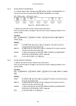
To set f Stop, press F•1 CINELITE DISPLAY to select f Stop and then press F•2 f Stop
SETUP.
On the f Stop screen, luminance levels are displayed using f-stop (exposure) values.
The measured f Stop value for a group of measured points is typically displayed using white,
but it will be displayed using yellow when it corresponds to a luminance level of 80 % or
more. Additionally, f Stop values that correspond to luminance levels equal to or less than
0 % can not be measured. They are displayed in yellow as “****.”
PIC
→
F•4 CINELITE
→
F•1 CINELITE DISPLAY
→
F•2 f Stop SETUP
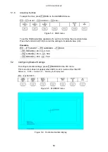
Figure 5-14 f Stop screen
1 Reference Position
The position where the cursors intersected when F•4 18% REF-SET was pressed is
displayed in red. This is the reference position for f-stop measurement.
2 Cursor
You can set up to three measurement points. The cursor coordinates are indicated
using sample numbers and line numbers. Additionally, The f Stop value relative to the
reference point is displayed at each point.
3 Gamma Correction Value
The gamma correction value that you selected using F•5 GAMMA SELECT appears
here.
4 Reference Value
The f Stop value at the reference position appears here. The value immediately after
you have pressed F•4 18% REF-SET is zero, but it will change when the picture
changes.
Summary of Contents for LV 5480
Page 15: ...2 VIDEO SIGNAL WAVEFORM DISPLAY 7 SCALE UNIT HDV SDV SCALE UNIT HD SD SCALE UNIT 150 ...
Page 38: ...2 VIDEO SIGNAL WAVEFORM DISPLAY 30 COLOR MATRIX XYZ COLOR MATRIX GBR COLOR MATRIX RGB ...
Page 98: ...5 PICTURE DISPLAY 90 STATUS INFO ON Figure 5 34 Turning the information on and off ...

