5. PICTURE DISPLAY
85
5.7.2
Configuring the Measurement Window
To display a window for measuring video noise on the picture display, follow the procedure
below. The size and area can be set in units of pixels and lines.
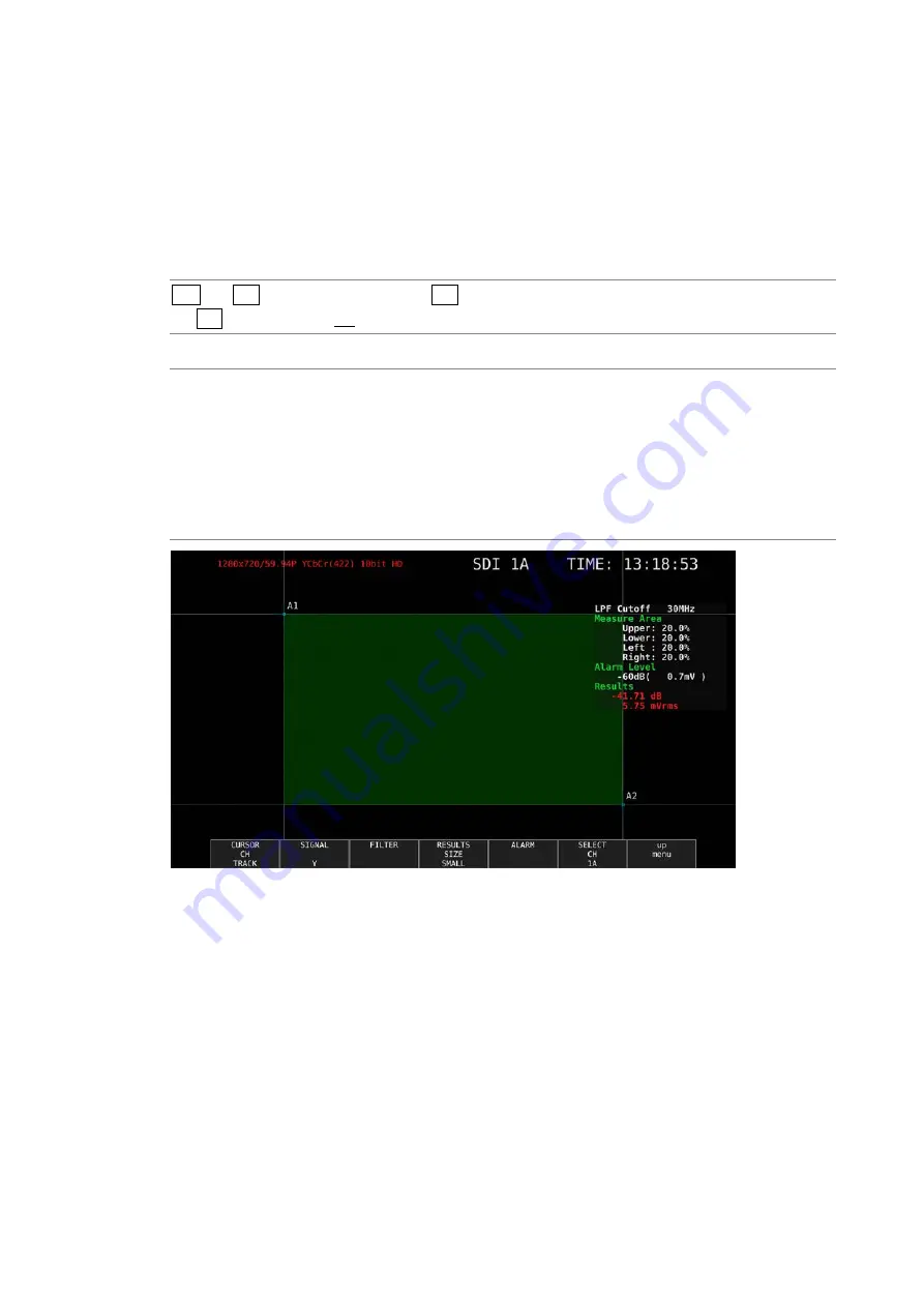
The green area defined by the diagonally opposite cursors A1 and A2 becomes the
measurement window.
Set this with the video noise meter turned on.
Procedure
PIC
→
F•3 LINE SEL / NOISE
→
F•4 NOISE SETUP
→
F•1 CURSOR CH: A1 / A2 / TRACK / OFF
Settings
A1:
Select cursor A1 for setting the measurement window. Use the V POS and H
POS knobs to adjust the position of the cursor.
A2:
Select cursor A2 for setting the measurement window. Use the V POS and H
POS knobs to adjust the position of the cursor.
TRACK:
Moves the measurement window. Use the V POS and H POS knobs to adjust
the positions of cursors A1 and A2 simultaneously.
OFF:
Turns off the cursor A1 and A2 display.
Figure 5-29 Measurement Window
*
Set the measurement window in an area where the average video level is uniform. If you include dark
areas in the video caused by the effect of the lens or areas where the video signal of the object is not
flat, accurate video noise measurement may not be possible.
*
There may be cases in which accurate video noise measurement is not possible due to overshooting,
undershooting, or ringing occurring in the rising or falling edges of the waveform depending on the
input video signal. If this happens, set the measurement window a few percent inside of the rising or
falling section.
Summary of Contents for LV 5480
Page 15: ...2 VIDEO SIGNAL WAVEFORM DISPLAY 7 SCALE UNIT HDV SDV SCALE UNIT HD SD SCALE UNIT 150 ...
Page 38: ...2 VIDEO SIGNAL WAVEFORM DISPLAY 30 COLOR MATRIX XYZ COLOR MATRIX GBR COLOR MATRIX RGB ...
Page 98: ...5 PICTURE DISPLAY 90 STATUS INFO ON Figure 5 34 Turning the information on and off ...


